Subjects:
- Preface
- Classic Coolant Temperature Gauge
- NTC temperature sensor
- Diagnosis at the temperature sensor
Preface:
There are a large number of temperature sensors in a vehicle:
- coolant temperature;
- oil temperature;
- interior / outside air and intake air temperature (possibly processed in air mass meter);
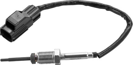
- exhaust gas temperature;
- battery temperature on vehicles with hybrid or all-electric drive.
The above temperature sensors provide the control unit of the respective system with information. For example, the engine control unit uses the signal from the coolant temperature sensor to injection, inflammation, idle control, EGR operation (if applicable) and the cooling fan control according to the temperature. At a low temperature, injection enrichment takes place and the EGR is controlled to bring the engine up to operating temperature faster. At a higher temperature, the control unit switches on the cooling fan relay. The most commonly used temperature sensors are according to the NTC principle.

In addition to sensors that send information to the control unit, there are also security sensors that function without additional electronics. At such a PTC sensor the ohmic resistance increases with increasing temperature. An electric motor (such as the wiper or window motor) and a mirror glass are equipped with a PTC sensor. In some cases, a PTC sensor is used as a temperature sensor, but most of the time we come across the NTC.
Classic coolant temperature gauge:
On older cars without control units and NTC temperature sensors, the coolant temperature transmitter works with a bimetal. The picture shows the components of the bi-metal meter. A stabilized voltage source of around 10 volts is connected to the meter. The bi-metal in the meter warps as soon as a (larger) current flows. This takes the pointer along.
In the engine block is a temperature sensor with a bi-metal.
The temperature gauge comes into contact with the coolant in the engine.
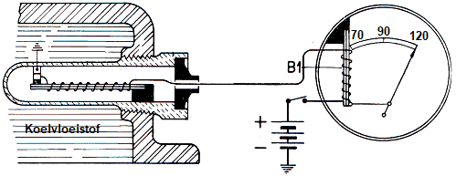
The temperature at which the tips open depends on the coolant temperature and the amperage. The average current then becomes dependent on the motor temperature. In some cases, the pointer is in the maximum position when the ignition is switched off. The bi-metal is then straight.
NTC temperature sensor:
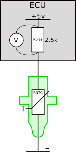
The following image shows a simplified schematic of the ECU and temperature sensor. The sensor (RNTC) has two wires. The plus wire is connected to the ECU and the negative wire to ground. There is a bias resistor in the ECU. The bias and NTC resistors are connected in series. The ECU supplies the series circuit with a voltage of 5 volts.
In a series circuit, the voltage is distributed across the resistors. Part of the 5 volts is taken up by the bias resistor. The other part houses the NTC sensor.
The bias resistor has a fixed resistance value; usually around 2500 ohms (2,5 kilo-ohms). The resistance of the NTC depends on the temperature. The voltage absorbed by the NTC resistor therefore depends on the temperature.
The ECU measures the voltage drop across the bias resistor. With a temperature change, the voltage across RNTC changes and with it the voltage across the bias resistor. After all, the voltage in a series circuit is distributed over the resistors; if the RNTC absorbs 0,3 volts more, the voltage across Rbias drops 0,3 volts.
The voltage measured across the bias resistor is what the ECU translates into a temperature. In fact, we now apply the NTC characteristic, with the voltage on the X-axis instead of the temperature.
At a high temperature, the least resistance change takes place. The line in the characteristic drops faster at a temperature of 0 to 20 degrees Celsius than from 40 to 60 degrees Celsius. For this reason, manufacturers often use a second bias resistor for the coolant temperature sensor. The bias resistors are connected in parallel and each has a different resistance value.
With increasing temperature, the ECU switches to the other bias resistor. This gives us a second NTC characteristic. The second characteristic will have a large resistance change at a high temperature. This allows us to measure over a wider range and accurately determine the temperature during both the warm-up phase and at operating temperature.
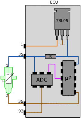
The following figure shows the actual circuitry in the ECU containing the 5 volt voltage stabilizer (78L05), bias resistor (R), the analog-digital converter (A/D converter) and the microprocessor. More information about the analog signal transmission, such as from the temperature sensor, can be found on the page: sensor types and signals.
Diagnosis at the temperature sensor:
Faults with the coolant temperature sensor can lead to the following complaints:
- bad starting of the engine due to eg extra injection for a cold engine, when in reality it is already warm;
- overheating: due to a value that is too low, the PWM-controlled cooling fan starts too late or does not start;
- the engine does not idle properly after a cold start;
- as the engine warms up, the idle speed increases;
- exhaust gas emissions are no longer in order;
- black smoke from too rich a mixture;
- hesitation and stuttering when the engine is cold;
- the air conditioning cannot be turned on.
Often the above complaints are in combination with an engine malfunction light, but that is not always the case. Also, if a fault occurs in which the coolant temperature sensor signal is within tolerances, no error code will be generated.
In reality, the software in the engine-ECU constantly checks whether the signal is plausible: in case of strong deviations from other temperature sensors, or a (too) strong increase or decrease in the temperature, the signal is considered "not plausible". considered. This will result in an error code.
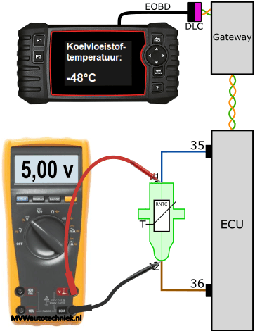
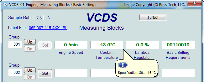
The coolant temperature can be read by means of diagnostic equipment (usually a cheap OBD reader or an interface with software for the telephone is sufficient for this).
In the image we see a temperature of -48 °C.
The diagnosis program (in this case the measured value blocks in VCDS) often also provides a target value that the temperature must meet. In current operating conditions, the temperature should be between 80 and 115 degrees Celsius.
If we suspect that a sensor reading is incorrect, we can check the voltages with a multimeter. First we measure the voltages across the sensor at three different temperatures. In the next three images we see a readout computer that is connected to the gateway via the DLC (Dat Link Connector) via CAN bus. The gateway also communicates with the engine ECU via CAN bus.


The section “NTC temperature sensor” above describes that the temperature sensor is in series with a bias resistor in the ECU. The voltage of 5 volts is distributed between the bias resistor and the NTC resistor in the sensor housing. When we measure a voltage of 2,3 volts across the sensor, the voltage across the bias resistor is 2,7 volts (2,3 + 2,7 = 5 volts). The voltage of 2,7 volts is shown in the A/D converter translated into a temperature in the interface electronics of the ECU. When the motor is warm, the voltage across the bias resistor rises; this can be seen in the last measurement. In that situation, this voltage is 4,58 volts.
The images below show the live data and measured values with an interrupted ground wire between the sensor and the ECU. The readout computer shows a temperature of -42 degrees Celsius: the ECU measures a voltage of 5 volts across the bias resistor. The ECU generates one or more error codes with descriptions about the sensor;
- signal implausible;
- signal below lower limit value;
- short circuit with plus.


Because as a result of the interruption no more current flows, the NTC no longer absorbs voltage. The voltage difference between pin 1 of the sensor and pin 36 of the ECU is 5 volts: this is the supply voltage of the sensor. 35 volts is supplied via pin 5. Because the sensor does not absorb any voltage, we measure a difference of 2 volts between pin 36 (ground connection) sensor and pin 5.
In the case where we measure a voltage of 5.0 volts across the temperature sensor, (see the following figure) we are measuring the total applied voltage across the component. We are now dealing with an interruption in the temperature sensor. The voltage drop across the positive and ground wires is 0 volts.
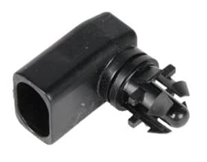
When we unplug the temperature sensor and measure with the multimeter in the plug, the same value appears on the multimeter's screen.
With the outcome of this measurement, it is clear that we need to replace the temperature sensor.