Subjects:
- General
- Ignition coil
- Conventional Contact Point Distributor Ignition
- Computer controlled ignition
- Combustion pressure and ignition timing
- ignition advance
- Dwell time
- DIS ignition
- One ignition coil per cylinder
- Measuring primary ignition image with the oscilloscope
General:
In a petrol engine, the fuel/air mixture must be ignited at the end of the compression stroke. This happens because the candle gives a spark. In order for the spark plug to spark, a voltage between 20.000 and 30.000 volts is needed. An ignition coil converts the battery voltage (around 12 to 14,8 volts) into this high voltage.
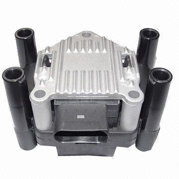
In older systems, there is often 1 ignition coil screwed somewhere on the engine block, which is connected to the spark plugs by means of spark plug wires. Newer engines often have pin coils. Each spark plug has its own ignition coil. The number of ignition coils on the engine can be easily recognized by the presence of spark plug wires. If there are spark plug wires to each cylinder, the car has 1 fixed coil or a DIS coil. If there are no spark plug wires, each spark plug has a separate ignition coil. Often an engine cover has to be disassembled to see this.
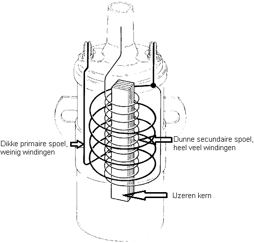
Ignition coil ignition:
An ignition system uses an ignition coil. Regardless of the type (conventional or computerized), the principle is the same. In the ignition coil there are 2 coils of copper wire around an iron rod (core). The primary coil (on the ignition side) has few turns of thick wire. The secondary coil has many turns of thin wire. The primary coil has a voltage of 12 volts. A current of 3 to 8 Ampere is sent through this primary coil. This generates a magnetic field. When this magnetic field disappears, a voltage of 250 to 400 volts is generated in the primary coil. Due to the difference in the number of windings, a voltage of up to 40.000 volts is generated in the secondary coil.
The primary coil of the ignition coil has an ohmic and inductive resistance. The ohmic resistance can be measured with the multimeter, or calculated from the current or voltage measurements. The inductive resistance refers to the magnetic field developed in the primary coil and depends on the rate at which the current changes and the magnetic properties of the coil (the L value). Each coil has a fixed L value, which depends on the number of turns and the dimensions of the coil and the properties and dimensions of the core.
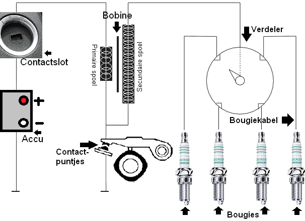
Conventional distributor ignition with contact points:
The conventional ignition system consists of a single coil that is switched on and off with contact points, coil cable, spark plug wires and a mechanical distributor with ignition timing advance.
At rest, the contact points are closed. A current flows through the primary coil, via the contact points to ground. At that moment, a magnetic field is present in the primary coil. When the tab lifts the lever, the contact between the contact points is broken and an induction voltage is created. This induction voltage is amplified in the secondary coil and passed on to the distributor via the ignition coil cable. The tab in the distributor points to one of the connections of the spark plug wires. The voltage is passed on to the spark plug, which produces a spark.
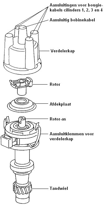
The ignition coil transmits a high voltage via the connection of the ignition coil cable to the rotor in the distributor. The rotor in the distributor rotates at half the crankshaft speed. This is made possible by either a direct connection between the crankshaft and the distributor (as shown in the figure), depending on the construction, or by the rotor being driven directly by the camshaft. After all, the camshaft already rotates at half speed relative to the crankshaft. The image shows an exploded view of the distributor.
The rotor is sensitive to maintenance. The contact particles between the rotor and the distributor cap will eventually corrode, causing the quality of the spark plug to deteriorate. By occasionally sanding away the corrosion, or by replacing the worn parts, the quality of the spark remains optimal. Turning the distributor cap on the rotor adjusts the ignition timing.
Computer controlled ignition:
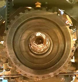
Modern cars are equipped with computer-controlled ignition systems. The engine management system controls the ignition coil. A pulse generator (crankshaft position sensor and optionally a camshaft position sensor) produces a reference pulse that is synchronous with the crankshaft or camshaft. In a ring or on the pulley there is often a missing tooth that serves as a reference point. The image shows the machined crankshaft pulley from the Mega Squirt project. The pulley has 36 teeth, 1 of which has been ground away. That is why it is also called a 36-1 reference wheel. At every 10 degrees, 1 tooth passes by the sensor (360/36).
Whenever the missing tooth rotates past the sensor, a signal is sent to the ECU.
This reference point is not top dead center (TDC) as the name often suggests. In reality, this reference point is between 90 and 120 degrees before TDC. This means that when there is no ignition advance, the ignition pulse occurs 9 to 12 teeth after the reference point.
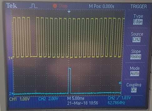
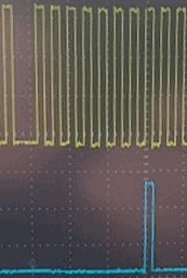
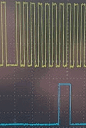
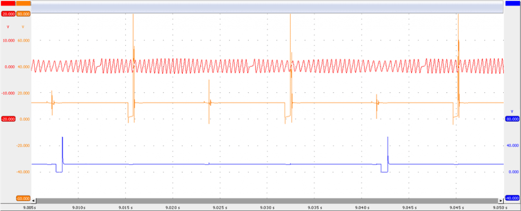
The figure shows the crankshaft signal (yellow) in relation to the ignition coil drive pulse (blue). In the crankshaft signal, the missing tooth is visible where the pulse is missing. On this engine, the missing tooth is 90 degrees before TDC (that is 9 teeth of the pulse wheel).
Between the missing tooth (reference point, yellow) and the actuating pulse (blue) 8 teeth are visible; there is 10 degrees pre-ignition here.
Bringing forward the ignition has to do with the burning rate; the combustion takes time to reach its maximum combustion pressure. This maximum combustion pressure is optimal at a crankshaft position of 15 to 20 degrees after TDC. This should be optimal under all operating conditions. The following paragraphs explain the influence of the ignition timing on the combustion pressure, how the ignition advance takes place and how you can read the dwell time in the scope image.
Combustion pressure and ignition timing:
The ignition system must ensure that the mixture in the cylinder space ignites at the correct time. The combustion pressure should be at its highest when the piston has passed TDC. Because there is time between ignition and ignition of the mixture (that is where the maximum combustion pressure is reached), the mixture must be ignited well before TDC. In short, the spark plug must have sparked before the piston has reached TDC.
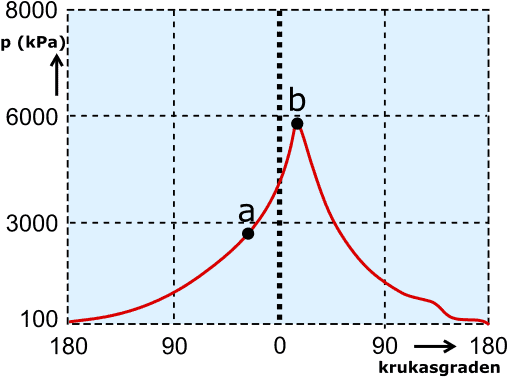
In the following diagram we see the pressure development (red line) in relation to the crankshaft degrees. At point a, the spark plug sparks. The piston moves further to TDC (0) and the combustion pressure rises. The maximum combustion pressure is reached approximately 10 to 15 degrees after TDC (at point b).
- if point b moves too far to the left, the mixture will ignite too early and the piston will be held back from moving up;
- when point b is moved to the right, combustion takes place too late. The piston has already moved too far to the ODP. The power stroke is no longer effective enough.
Ignition advance:
In order for the pressure peak to occur at the correct crankshaft position, it is important to advance the ignition when the RPM is increased. Point b (the maximum combustion pressure) must not be moved. Point a (ignition moment) is shifted to the left or right when the ignition point is advanced and departed. The combustion time depends on the fill level of the engine and the current mixing ratio. The ignition advance is therefore different for each engine. This is also the reason why the crankshaft reference point is set a few degrees before TDC: between the reference point and TDC there is time to calculate the ignition advance.
With a DIS ignition coil (described further down the page), the crankshaft position sensor is sufficient to determine the ignition timing. The first pulse after the missing tooth is used, for example, to charge the secondary coil of cylinders 1 and 4. Then the number of teeth is counted (in this case 18) to generate the pulse for the secondary coil of cylinders 2 and 3. When the engine is equipped with COP ignition coils, one reference point is not enough. In that case, a camshaft position sensor is needed to detect multiple reference points.
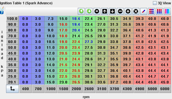
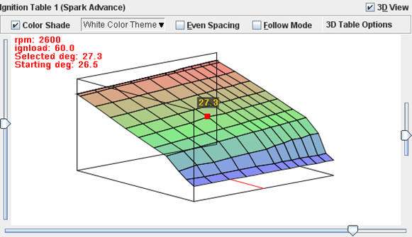
The two images below (ignition advance table and the 3D view) show the ignition map settings in the Mega Squirt project. These are called the lookup tables, reference or core fields.
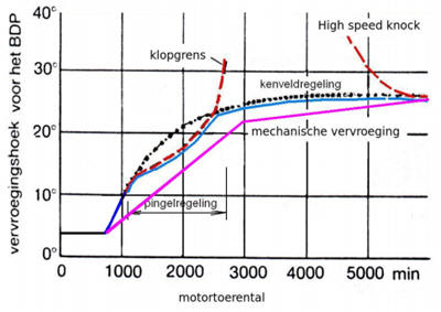
The ignition advance is determined by the engine configuration. The graphs show the full load ignition advance curves with (conventional) mechanical distributor ignition (pink line) and a computer controlled system (blue line). The kink in the pink line is the point where the vacuum advance takes effect. Furthermore, the lines are straight; this is due to mechanical limitations. This can be controlled more accurately with a computer-controlled system; therefore, the ignition curve is like a curve. Between 1200 and 2600 rpm, the blue line is slightly drawn down; this has to do with the partial load knock area. Furthermore, it can be seen that both the conventional and the computer-controlled advance lines end at about 25 degrees. The advance may not increase further, because then there is a danger of the “high speed knock”, or the knock area at a high speed.
The ignition map serves as the basis for the ignition advance. From this point on, the engine management system will try to advance the ignition as much as possible. Too much advance will lead to pinging; this is registered by knock sensors. The moment the knock sensors register that the engine is tending to knock, the engine management system will again leave the ignition timing a few degrees. Then it will be advanced again until the knock sensors give a signal.
Dwell Time:
When the primary current is switched on, a magnetic field is built up. The current through the coil will not immediately reach its maximum value; This takes time. In the coil there is a resistance which is obtained from an opposing induction voltage. Also, the current will not rise further than 6 to 8 Amps. Sufficient energy has been generated in 2,3 milliseconds for the spark plug to jump a spark sufficient to ignite the air-fuel mixture. The point t=2,3 ms is the ignition time. We call the current build-up from time t0 to t=2,3 ms the charging time of the primary coil, or the dwell time.
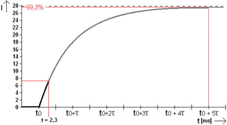
Current build-up in the primary coil stops at approx. 7,5 Amps. The current must not increase further, because then the primary coil may become too hot. When the vehicle's on-board voltage drops, more time is required to charge the primary coil. The ignition timing does not change. Therefore, loading has to be started earlier. This can be seen in the figure, where the green line represents the turn-on phenomenon of the coil at a lower voltage. The charging process starts earlier (delta t) and ends at the same time as the black line at 7,5 A.
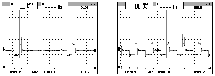
The ignition coil control changes; the width of the drive pulse affects the charging time of the primary coil. The longer the pulse, the longer the coil has time to charge.
In both images, the ignition occurs at the eighth tooth (80 degrees BDC). The right image shows the longer dwell time.
DIS ignition:
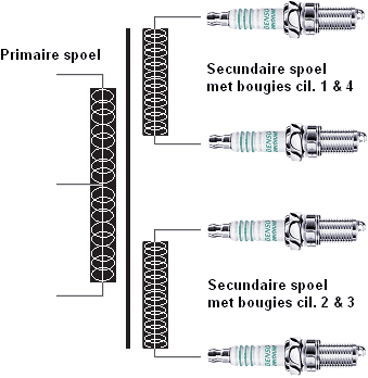
DIS stands for Distributorless Ignition System. It is, as the name suggests, an electronic distributorless ignition. The signal to ignite comes directly from the ECU, making it a computer-controlled ignition. With this ignition system, 2 ignition coils are combined in 1 housing. Each ignition coil provides the spark for 2 cylinders. There is a one coil ignition coil mounted on cylinders 1 and 4, and the other coil is mounted on cylinders 2 and 3.
As an example, let's take the DIS coil with the connections for cylinders 2 and 3. There is no rotor present, which means they will both spark at the same time. Cylinder 2 is at the end of the compression stroke and the ignition coil provides a spark to ignite with mixture. This means that the ignition coil also sparks on cylinder 3, which then starts the intake stroke, but because it now has no combustible mixture, it does not matter. Later, when cylinder 3 is engaged in the compression stroke, cylinder 2 will be engaged in the intake stroke and will then get the unnecessary spark. The dead spark in the cylinder where no combustion takes place does not cause the spark plug to age more quickly. The spark then only needs a voltage of 1kV (1000V) instead of 30kV when burning a mixture.
The advantage of the DIS coil is that no maintenance is actually required. The ignition coil is maintenance-free. The disadvantage of this coil is that moisture sometimes penetrates between the cable and the connection shaft in the coil. Moisture causes corrosion of the contacts, which turn white or green. The spark voltage decreases due to the large voltage loss caused by the corrosion. The engine will be able to shake and vibrate slightly, without there actually being a malfunction in the memory of the ECU. In case of a complaint like this, it is wise to remove the cables from the ignition coil one by one (while the engine is off!!) and to see if the contacts are nicely golden and there are no traces of corrosion in the cable and in the shaft can be seen. The corrosion is very aggressive and will slowly return after cleaning. The best solution is to replace the complete ignition coil with the relevant cable.
One ignition coil per cylinder:
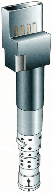
With this ignition system, the (rod) ignition coils, also known as COP (coil on plug) ignition coils, are mounted directly on the spark plug. Again, the engine control unit (ECU) controls the ignition. Both amperage and ignition timing are calculated by the control unit. It works like an older ignition coil; this ignition coil also has a primary and secondary coil. The primary coil is supplied with voltage via the plug at the top and interrupted internally via a transistor.
The disadvantage of these ignition coils is that they are mounted in the spark plug shaft and therefore become extremely hot. Although they are made for that, they still want to break. You can recognize that a car skips a cylinder and then the engine starts to shake. When this happens, the lambda sensor will recognize that an ignition coil is not igniting the fuel and the fuel injection to the affected cylinder will be stopped. The cylinder then no longer works at all. This prevents unburnt fuel from entering the exhaust, which will destroy the catalytic converter. A faulty ignition coil can often be identified by the engine running very erratically (and the engine light is on, although there are many reasons why this light comes on).
More information and causes of cylinder overturning can be found on the page cylinder transfer.
If it is suspected that the ignition coil is defective, the primary ignition image can be viewed with the oscilloscope, if the engine is in emergency mode and the ignition and injection have been switched off while the engine is running.
Measuring primary ignition image with the oscilloscope:
The ignition coil generates the voltage so that a strong spark can develop at the bottom of the spark plug. The ignition coil must generate a voltage of approximately 30.000 to 40.000 volts in order to make a spark jump in the spark plug. To do this, an ionization voltage of 300 to 400 volts must be generated in the primary coil. In the course of the voltage through the primary coil we can see whether this process is going well. The voltages of the primary and secondary coils are passed to each other, although the levels in the secondary coil are about 100x higher. This makes it possible to see in the primary voltage curve whether the ignition coil is OK and whether the spark plug is sparking properly. The scope image below was measured on the primary coil of an ignition coil.
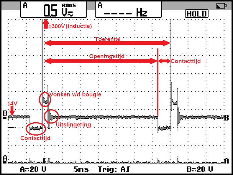
From left to right:
- 14 volts: at rest we measure 14 volts on the positive and ground side of the coil in the ignition coil;
- Contact time: the primary coil is grounded on one side. A differential voltage of 14 volts is created between + and ground, causing current to flow through the coil;
- 300 Volts (Inductance): The output stage in the ECU or ignition module terminates control and an inductance of approximately 300 volts occurs in the primary coil. We call this the ionization voltage. A voltage of 30.000 volts is generated in the secondary coil. This voltage is necessary to make the air between the electrodes of the spark plug conductive and to make a spark jump;
- Sparks from the spark plug: from the spark line, we can see that the spark plug is sparking;
- Ejection: this is where the residual energy flows. It depends on the LCR value of the circuit (L value of the ignition coil and the capacitance of the capacitor).
By the opening time in the scope image we mean the opening time of the contact points. This no longer applies with a computer-controlled ignition. We can, however, determine the rotational speed on the basis of the point at which the ionization voltage of the second spark comes into the picture. The scope images below show the primary ignition images at low speed (left) and high speed (right).
With an oscilloscope we can display the ignition image and injection image relative to the crankshaft signal. The reference wheel contains one reference point. An ignition moment occurs after every revolution of the crankshaft. We know that the crankshaft must turn two rotations for one full duty cycle. From this we can recognize that we are dealing with a DIS coil. So a “wasted spark” takes place. The injector images confirm this: the injection takes place every second crankshaft revolution.
If it is suspected that an ignition coil is defective, viewing the secondary ignition image can determine whether there is a problem in the secondary ignition. The resulting image shows the ignition image of cylinder 6 (blue) and of cylinder 4 (red) in which a fault is present. The explanation follows below the image.
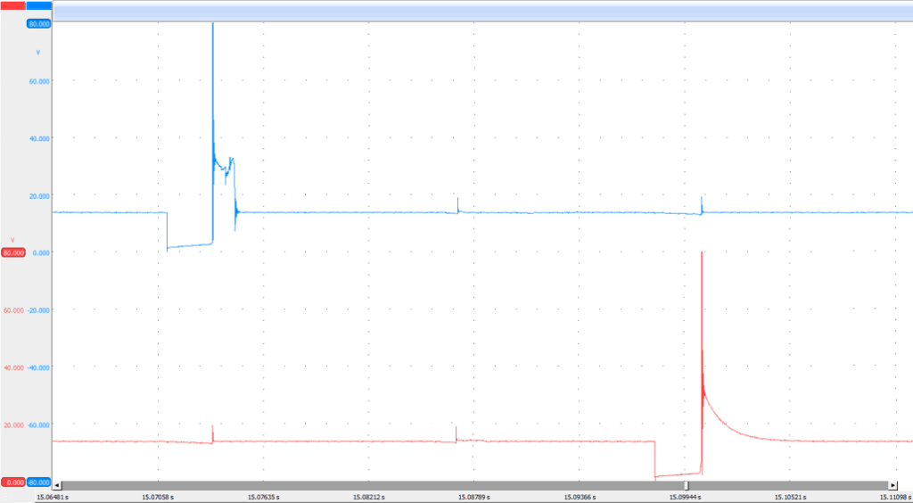
The primary image of cylinder 4 shows the ionization voltage, but then the energy flows away. The image now resembles the typical voltage curve of a magnetic coil injector. What can we recognize in this image:
- Cylinder 6 (blue) is OK. We use this image as a reference;
- Cylinder 4: The ionization voltage is OK. Energy is generated in the primary coil. The primary coil is good;
- Engine ECU or external ignition module control is OK;
- The secondary gradient is not visible;
- Thus, the primary and secondary coils do not exchange energy;
- The secondary coil is interrupted.
Experience shows that the secondary coil of an ignition coil can fail due to heat. We can detect this defect with an oscilloscope. Please note: if the motor has gone into emergency mode, the control may be terminated. Therefore, carry out the measurement immediately after or while starting the engine.