Subjects:
- Fuel trims (LTFT and STFT)
- The origin of the STFT and the transition to the LTFT
- Possible causes of a mixture that is too rich (negative fuel trim)
- Possible causes of a mixture that is too lean (positive fuel trim)
- Possible cause of both positive and negative fuel trim on two cylinder banks engine
Fuel trims (LTFT and STFT):
Fuel trims are formed from the data from the oxygen sensor. The fuel trims are used on a gasoline engine to maintain the ideal air/fuel ratio for complete combustion. This amounts to 14,7 kg of air to 1 kg of fuel and we call this the stoichiometric mixing ratio.
Fuel trims provide a correction factor to adjust the base amount of fuel injected when needed. The wear and contamination of engine parts, sensors and actuators is taken into account. With the help of the fuel trims, the exhaust gas emissions over the entire life cycle of the car are kept within the legal standards. With a positive fuel trim, the ECU tries to make the lean mixture richer. With a negative fuel trim the opposite; the mixture that is too rich is made leaner. The control pulse of the injector will hereby be made longer or shorter.
The following image shows the fuel trims for a rich mixture (-25%) and for a lean mixture (+25%).
- The negative fuel trim means that the injectors have to inject less fuel.
- The positive fuel trim means that the injectors have to inject more fuel.
With a fuel trim of 0%, no compensation needs to be carried out, because at that moment the stoichiometric mixing ratio is in effect.
There are two types of fuel trims;
- Short Time Fuel Trim (abbreviated as STFT) is what engine management does right now to adjust the air/fuel mixture. The STFT changes constantly while the engine is running due to short term adjustments and temporary changes. We call this the “short-term adjustment”. The STFT is reset when the engine is turned off.
- Long Time Fuel Trim (abbreviated as LTFT) consists of adaptive learning values that are formed from the STFT over a longer period of time. This is also known as the “long-term adjustment”. The LTFT is stored in the “Keep Allive Memory” (KAM) which is not reset when the engine is turned off and on. The LTFT is stored in the readiness test. Erasing is only possible with diagnostic equipment or by removing a battery terminal. The latter is not always possible.
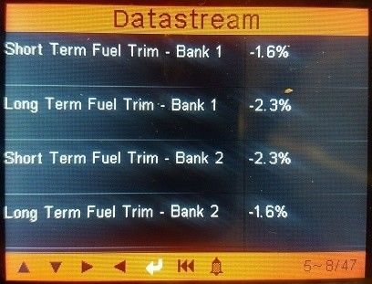
Both the STFT and LTFT values should be as close to 0% as possible. Depending on the condition and operating conditions of the engine, the LTFT values can vary from 5 to 8%. The LTFT and STFT values indicated by the reading device in the figure below are within tolerances and are therefore OK.
The above image shows the STFT and LTFT of “Bank 1” and “Bank 2”. So this engine has two cylinder banks, so it will be a V-shape engine. On the engine is often indicated which cylinder bank number 1 and number 2. Otherwise, consult the engine specifications if in doubt.
There is often a problem with fuel trim values that are more than 10%. An error code does not have to be stored yet. At fuel trims lower than -20% or higher than 20%, the engine management will store an error code related to a too rich or too lean mixture.
The LTFT values remain constant for a long period of time because these values have been measured over a long period of time and stored in the readiness test (see the OBD page). The STFT values often jump across the screen during varying engine loads, due to a throttle opening or closing further.
Studying the fuel trims can be helpful in making diagnoses. In case of problems where no faults are present, or when the fault is not related to the complaint, the fuel trims can offer a solution. At an LTFT of slightly less than 10%, no interference is stored, but it does give an indication that the mixture is on the lean side.
The origin of the STFT and the transition to the LTFT:
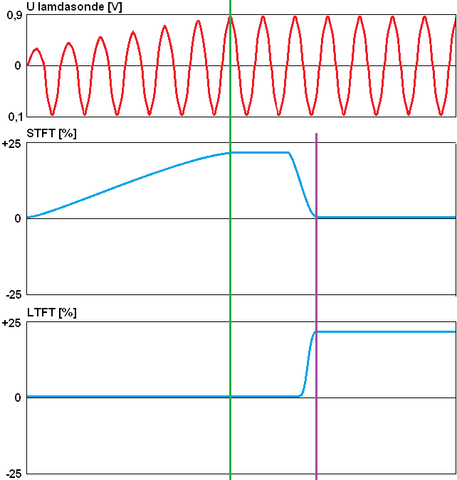
The following figure shows at the top the voltage curve of the oxygen sensor (zirconium/jump sensor), in the middle the short term, and at the bottom the long term adjustment.
The oxigen sensor signal does go negative (0,1 volts) but not enough positive (0,25 volts). The engine management recognizes this as a mixture that is too lean.
To make the mixture richer, additional fuel is injected. This correction is reflected in the percentage of the STFT: the blue line is rising. At that point, nothing happens to the LTFT yet.
As the STFT rises, we see that the oxygen sensor measures an increasingly rich mixture. The STFT continues to rise until the voltage has reached the desired value of 0,9 volts. This point is indicated by the green vertical line.
Now that the STFT has assumed a certain value, it is held constant for a certain amount of time. If it turns out that the signal from the oxygen sensor is OK as a result, the LTFT takes over the value of the STFT. The purple vertical line indicates the moment of this transition.
The STFT drops to 0% and the LTFT has taken over the positive value. The percentage exceeds the limit of 10%. The MIL will illuminate. Thanks to the correction factor, the motor will continue to run properly.
After the repair of the problem, the learning values can be deleted. This is not necessarily necessary: the fuel trims are corrected automatically.

Example: A vacuum leak has caused an LTFT of 7,8%. A test drive will be made after the repair. Because there is now no more false air, the correction now causes a mixture that is too rich. The STFT picks this up immediately and goes negative. The following four images were taken at different times during the test drive.
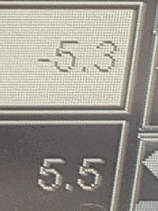
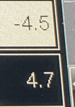


The LTFT in the preceding figure is 5,5%. To compensate for this, the STFT is -5,3%. This can also be seen in the second, third and fourth images: the positive LTFT value is offset by a negative STFT value.
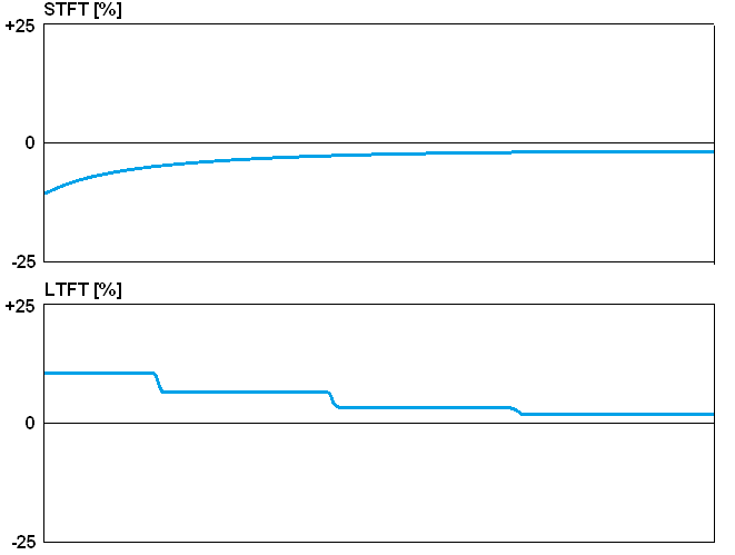
The following graphs indicate the percentage relative to time.
- Before the repair, the STFT was 0% and the LTFT was positive;
- During the test drive after the repair, the STFT starts negative to cancel the LTFT value
- The LTFT decreases stepwise: between each correction the value remains constant for a while;
- The LTFT eventually becomes 0%
It is important for a technician to look at this: have the values of the STFT and LTFT mirrored each other after the repair:
- +15 and -15, or
- -5 and +5.
This indicates that the result is 0%, so the repair was successful.
Possible causes of a mixture that is too rich (negative fuel trim):
- Faulty fuel injector; if the injector leaks, more fuel will end up in the combustion chamber than the engine management has calculated and controlled.
- Problem in the air supply in the engine due to a heavily polluted air filter or blockage in the inlet.
- Problem with the oxygen sensor; a defect or a clogged hole with which the lambda probe measures the oxygen content in the outside air.
- Problem in the fuel supply due to a defective fuel pressure regulator or a fuel return problem.
- Incorrect coolant temperature.
- Problem with EGR.
- loss of compression.
- too small valve clearance.
Possible causes of a mixture that is too lean (positive fuel trim):
- Leakage in the exhaust pipe, so that not all exhaust gases are measured by the lambda sensor.
- Vacuum leakage in, for example, the engine inlet hoses (between the air mass meter and the intake valve), a ruptured crankcase breather hose, a ruptured hose from the vacuum brake booster, etc.
- Faulty fuel injector; this injects too little or nothing.
- Defective or soiled lambda sensor.
- Defective or soiled air mass meter.
- Restrictions in the fuel supply due to, for example, a clogged fuel filter
- Defect in the fuel pump not delivering enough fuel pressure.
Possible cause of both positive and negative fuel trim on a two cylinder bank engine:
An engine with two cylinder banks (V engine) has two exhaust manifolds and therefore also two (control) oxygen sensors that can determine the mixture ratio per cylinder bank. If the engine is equipped with one mass air flow meter and the fuel trims are read in the event of an engine failure (e.g. cylinder overturn), bank 1 may indicate a negative trim and bank 2 a positive trim, e.g.:
- sofa 1: LTFT -10
- couch 2: LTFT +12
In this case, a correction is made on bank 1 to make the mixture leaner (due to oxygen deficiency) and bank 2 richer (oxygen surplus). This could be due to incorrect distribution timing. In this case, check the timing of the crankshaft in relation to the camshafts. Please note that with the electrical timing control (check with the scope the ratio between crank and camshafts) there may be camshaft adjustment. You can also choose to carry out a mechanical check with a blocking tool. This does not apply to engines with two air mass meters (one for each cylinder bank).
Related pages: