Subjects:
- General
- Material
- Sodium Filled Valves
- valve guides
- Different types of valve control
- Valve mechanism with Indirect valve actuation
- Valve Mechanism with Direct Valve Actuation
- Adjust valve clearance
- Multi-valve technology
- Variable valve timing and valve lift
General:
There are valves in every combustion engine. There is always at least one inlet and one exhaust valve. These valves are driven by one or more camshafts by means of the distribution and ensure that fresh air can flow into the combustion chamber, the air is subsequently locked up during compression and can then leave the combustion chamber again. The flow of the intake and exhaust gases must be with as little resistance as possible.
The materials are therefore shaped as well as possible.
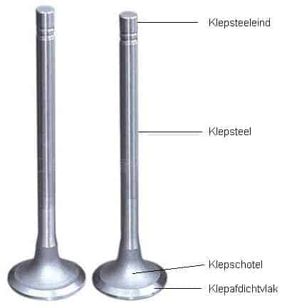
The valves are located in the cylinder head. The intake valve is often larger than the exhaust valve, because as much mixture as possible has to get into the cylinder. The exhaust valve should be smaller, because burned exhaust gases leave the cylinder after the exhaust stroke, when the piston pushes the gases out of the cylinder.
As an example, let's consider the four-stroke process of a gasoline engine. During the intake stroke of the engine, the inlet valve opens and an air-fuel mixture is drawn in with an indirectly injected petrol engine and only fresh air with a direct injected petrol engine. The air is drawn in as the piston moves downwards. The air that flows in takes up the space that is released. When the piston moves up again, the inlet valve will close. The mixture of fuel and air now has no place to go and is compressed. This is called the compression stroke. That is why it is important that the valves close properly. The mixture is ignited by the spark plug providing a spark. As a result, the piston is pushed downwards with a considerable force. This is called the power stroke.
On the exhaust stroke, the exhaust valve opens and the piston moves up. The burnt gases now leave the cylinder and go to the exhaust. When the piston is at the top, the exhaust valve closes and the intake valve opens. The piston goes down again and the intake stroke follows. In reality, the intake valve opens slightly earlier, so that the intake and exhaust valves are open simultaneously for a short time. This is called “valve overlap”. The speed of the burnt gases that leave the cylinder through the exhaust valve creates a negative pressure, so that the intake air is extra attracted. In this way more air can flow into the cylinder than if only the intake valve were to open and the piston moved downwards. The degree of filling is thus improved.
For a more detailed explanation of the four-stroke process, see the page “Operation petrol engine".
Material:
Valves are heavily loaded. Especially the exhaust valves, because they get very hot and can't be cooled much. The inlet valves are partly cooled by the cold intake air that enters the cylinder. The burnt exhaust gases with a temperature of up to 900 degrees Celsius flow past the exhaust valves. That is why exhaust valves are also made of a different material than inlet valves. Intake valves are often made of chrome nickel steel. Exhaust valves are often made of chrome silicon steel. To limit wear from high temperature conditions, the outer edges of the valve disc (the sealing surface) and the valve stems are armored with a layer of carbide alloy (stellite). The valves dissipate most of the heat through the valve disc and valve stem. Sodium filled valves have even better heat dissipation.
Sodium Filled Valves:
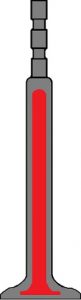
Exhaust valves are hollow inside. The hollow space is about 60% filled with sodium. Sodium is a metal that liquefies at a high temperature (from about 100 degrees Celsius). When the engine is running, the valve often moves up and down. The sodium in the valve is constantly flung back and forth and thus transports the heat. The sodium absorbs the heat from the valve disc and transfers it to the valve stem. With sodium-filled valves you can get a temperature drop of 80 to 100 degrees compared to non-sodium filled valves.
Intake valves do not need this, as these are already cooled by the incoming air.
In the picture, the gray surface represents the material and the red part represents the cavity filled with sodium.
valve guides:
The valves move up and down in the cylinder head. There must be a good seal between the valve and the cylinder head so that no oil can run from the cylinder head, down the valve stem and into an inlet or exhaust channel. There is always a small film of oil between the valve and the valve guide for lubrication. In the illustration, the valve guide is shown in orange.
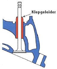
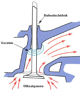
Blue smoke from the exhaust may be due to faulty valve guides. It is possible that the valve guides have become wider (see picture below) so that the valve even has play in the cylinder head. In this situation, oil can get past the valve, the intake or exhaust duct. At the top of the valve guide, the outside air pressure, or sometimes even overpressure due to a higher crankcase pressure, prevails. At the bottom of the valve guide, the gases flow to the exhaust manifold, providing a vacuum effect. The leakage is thus reinforced, because the oil is, as it were, sucked downwards along the valve stem. When the oil enters the exhaust manifold, it is not burned. The oil is heated up so that it partly evaporates. The result may be blue smoke coming out of the exhaust.
Valve guides can often be replaced separately. To do this, the cylinder head must be disassembled and the valve removed from the cylinder head. The valve guides can then be replaced. The valve guides cannot be replaced separately on all cylinder heads. Remanufacturers often have a solution for this. Ask for the possibilities of replacing valve guides at a reputable overhaul company.
Different types of valve actuation:
The valves can be operated in different ways. The image below shows five different versions. These different versions and the ways of adjustment are discussed further on this page.
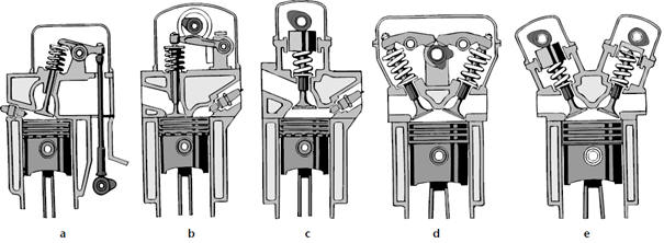
- A: Indirect valve control with rocker arms.
- B: Direct valve control with roller tow rocker arms.
- C: Direct valve actuation with hydraulic valve lifters.
- D: Direct valve control with rocker arms and multiple valves per cylinder.
- E: Direct valve actuation with hydraulic valve lifters and multiple valves per cylinder.
For engines without hydraulic valve lifters (A, B and D) it is necessary to periodically check the valve clearance. More about this in the chapter “Adjusting valve clearance” on this page. For engines with hydraulic valve lifters, adjustment of the valve clearance is not necessary and not possible; the hydraulic rams are filled with oil, eliminating the excess clearance.
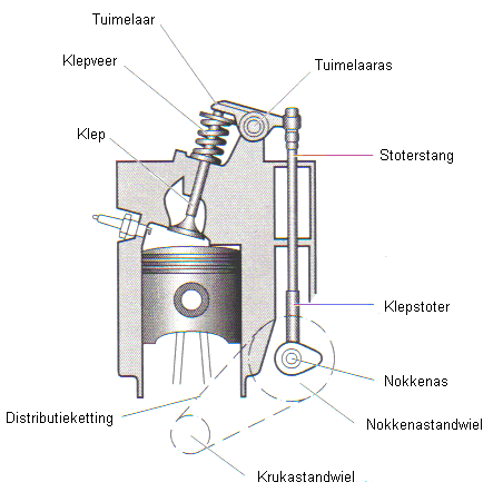
Valve mechanism with indirect valve actuation:
In the past, engines were carried out with an underlying camshaft. Nowadays, passenger car engines are only equipped with an overhead camshaft. The construction with the underlying camshaft is disappearing. The disadvantage of this construction is that these engines can handle less high speeds, because there is a lot of mass between the camshaft and the valve. At high speeds, there will be too much play and the valve will no longer open and close at the correct times.
The crankshaft drives by means of a small timing chain or belt to the underlying camshaft (see image below). The camshaft pushes the valve tappet and pushrod straight up. The right side of the rocker arm is pushed up. The rocker arm 'tumbles' around the rocker arm axle, pushing the left side down. This forces the valve downwards against the force of the valve spring. When the camshaft is rotated further, the valve spring presses the valve closed and the rocker arm returns to its starting position.
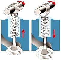
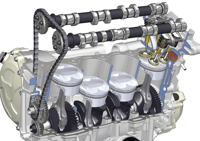
Valve mechanism with direct valve actuation:
The overhead camshaft is now only used in passenger cars. The camshaft is then placed in the cylinder head. The advantage of engines with an overhead camshaft is that they can handle higher speeds than with a lower camshaft.
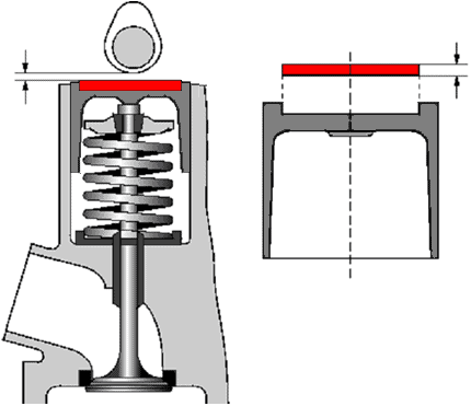
The above left image shows that the valve is closed because the valve spring is compressing the valve and the camshaft is turning clockwise. In the right image, the camshaft is twisted, causing the cam to push the valve down. The spring is now compressed, pushing the valve down. The moment the camshaft has turned further, the valve spring will push the valve back up. The valve spring exerts a counter pressure of approximately 20 kg.
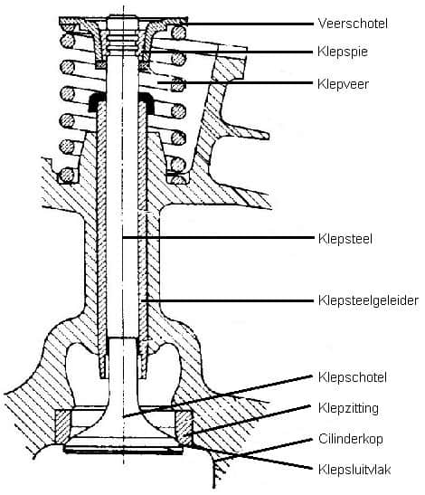
The figure shows a schematic representation of a valve with valve spring. Here you can clearly see on which part the valve rests on the valve closing surface of the valve seat. At the top are the spring seat (the part where the cam of the camshaft pushes the valve down) with the valve key and the valve spring below. The valve key serves as fastening of the valve. To remove the valve from the cylinder head, the valve keys must be removed. When disassembling, the spring plate must be pushed down against the force of the valve spring (special tools are available for this). The valve will then be free to move. By removing the two valve keys with a magnet between the spring seat and the valve stem, the valve can be removed from the cylinder head from below.
When mounting, care must be taken that the correct valve is mounted in the correct place. These may not be exchanged. When a new valve is placed, it will have to be sanded in with special abrasive paste. After storage, the valve will seal properly. The new valve can then be slid through the valve stem guide and the valve keys replaced. The valve spring can then be released again.
Adjust valve clearance:
There must always be a certain amount of clearance between the camshaft and the rocker arm or the top of the valve. This clearance gives the material the opportunity to expand. The clearance should not be too great; the valve then opens less far and for a shorter time. If the clearance is too large, it will take longer for the camshaft to press the valve open and the valve will close sooner. The clearance should also not be too small; the valve is then opened earlier and closed later. The valve is then open too long each time. The time that the valve is closed is therefore shorter; there is a chance that the valve cannot lose its heat to the valve seat of the cylinder head and therefore overheats. The valve can then burn.
Today almost all passenger cars are equipped with hydraulic valve lifters. However, there are still manufacturers that develop engines for which the valve clearance has to be adjusted. In cars from the 90s, the use of hydraulic valve lifters was not at all self-evident. So there are still plenty of vehicles on the road where the valve clearance must be checked periodically and adjusted if necessary. In the factory data you can often find at which mileage this should be done (often every major service). There are two different constructions to adjust the valve clearance; by means of shims and by means of adjusting eccentric bolts. These are both described below.
When the valves are adjusted, it is not allowed to just start at an arbitrary point. Close attention should be paid to the point when the valves are set to “tumble”. Tumbling means that the camshaft has just closed the exhaust valves and is about to open the intake valves. The moment cylinder 1 is tumbling, this means that it is at the beginning of the intake stroke. The piston of cylinder 1 is therefore at the top. Cylinder 1 and 4 are always in the same place in terms of height (just like 2 and 3 are at the same height, see image below). Since the firing order is 1-3-4-2 (remember the power diagram), it means that cylinder 4 is at the beginning of the power stroke. After cylinder 4 it is therefore cylinder 2's turn and then cylinder 3.
The image below shows the piston of cylinder 1 in the BPD. The cams face downwards; the intake valves have just closed and the exhaust valves are about to open. At that moment the valves of cylinder 4 can be adjusted; the cams are pointing upwards there.
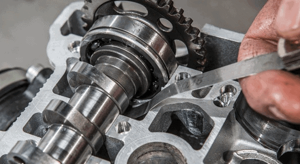
The valve clearance is measured with a so-called “feeler buddy“. The feeler gauge has various sizes with metal strips, each with a value of 0,05mm thicker than the other. By sliding a number of strips between the camshaft and the valve, you can check how much play is present. The relevant strip should not be pushed through too easily; the valve clearance is then greater than the value of the strip. If the strip does not fit in between or is very heavy and gets stuck, then the strip is too thick. Resistance may be felt when the strip is moved between them.
Adjusting valve clearance by means of shims:
The thickness of the shim, also called “shim”, determines the valve clearance in this case. In the image below, the shim is marked in red. By replacing the shim with a thicker one, the valve clearance will be reduced. There is then less space between the camshaft and the shim. Below the image it is explained how to adjust the valve clearance. To adjust the valves, the cam of the respective valve must be facing up as shown in the figure below. When the cam is twisted, incorrect measurements are made. When adjusting the valves of a four-cylinder engine, the following actions must be observed:
- Tumble cylinder 1 up = Set valves of cylinder 4.
- Tumble cylinder 2 up = Set valves of cylinder 3.
- Tumble cylinder 3 up = Set valves of cylinder 2.
- Tumble cylinder 4 up = Set valves of cylinder 1.
For example, the factory value of the above valve clearance may be 0,35mm. So there must be a space of 0,35mm between the shim and the camshaft when the cam is pointing up. With the feeler gauge the space between the two parts can be measured. If the 0,35mm strip goes through very easily without feeling any resistance, this means that the distance between the valve and the camshaft is greater than 0,35mm. In that case, the valve clearance is too large. When a strip of the feeler gauge of 0,45mm almost does not fit in between because a lot of force has to be put in to push it in, this strip is too thick. The actual clearance is then between 0,35 and 0,45 mm. A strip of 0,40mm can be slid in between just to be sure. If it starts, but it can be moved back and forth (resistance may be felt), then you know for sure; the valve clearance is 0,40mm instead of the prescribed 0,35mm.
Because the valve clearance is too large, a thicker shim must be mounted. Often the measurements are on the shims. In that case, read the value of the shim that is too thin. That is, for example, 2,75 mm.
The valve clearance is too large; the shim must be 0,05mm thicker than the one that is mounted, namely that of 2,75mm. The valve clearance is correct when a shim of (2,75 + 0,05) = 2,80mm is mounted. In that case, install the 2,80mm shim, turn the crankshaft two rotations so that the correct valves are tumbling again and check the valve clearance again.
Often there are special disassembly tools to make it easy to replace the shims. An example of this can be seen in the image.
Adjusting valve clearance by means of adjustable eccentrics:
A frequently used system is the adjustable eccentric. The adjusting screw can only be turned when the lock nut has been loosened by a quarter turn. When the adjusting screw is subsequently turned, the space between the valve stem and the rocker arm will immediately increase or decrease. By then tightening the locknut, the adjusting screw is locked again.
Here too, of course, the valves of the correct cylinder must first be turned on! By feeling the feeler gauge with the correct thickness (ie the same value as the factory value) between the valve stem and the rocker arm, it can be determined whether the valve clearance is too large, too small or correct. By turning the adjusting screw and moving the feeler gauge constantly in between, the correct position of the adjusting screw can be found where the valve clearance is correct. Then tighten the locknut and then check if the clearance is still the same. There is a high probability that the adjusting screw has turned slightly when tightening the locknut unless special tools specified by the manufacturer are used.
Multi-valve technology:
Every four-stroke engine has at least 1 intake valve and 1 exhaust valve. More powerful and more economical engines often have 2 intake valves and 2 exhaust valves. Some types have 2 inlet valves and 1 exhaust valve, or 3 inlet valves and 1 exhaust valve.
There are two main benefits of using multiple valves, namely:
- The valves will have a somewhat smaller diameter, which leads to a lower mass (less weight) per valve. The main advantage of this is that the valves do not float at a high engine speed. Floating valves mean that when the engine is running at a high speed (eg 5000rpm) the valves open and close so quickly that the valve springs no longer have time to close the valve. The valve therefore does not close completely on the valve seat. This can result in the piston hitting the valve, or the valve overheating because it can no longer give off heat to the valve seat. Due to the multiple valves, the valves are lighter and the valve springs have enough time to close the valve.
- Due to the lower mass per valve, the valves can be closed faster. This allows variable valve timing to be used, where the camshaft position is rotated at a particular engine speed or load.
Variable valve timing and valve lift:
Modern engines often use variable valve timing. Some motorcycle manufacturers also apply variable valve lift (eg BMW). These chapters are described separately on the pages: