Subjects:
- Engine management with self-diagnosis
- Control functions and control of the engine management
- VE and AFR tables for determining the amount of fuel required
- Adaptive learning memory
- The occurrence of an error code
- Customize the software
Engine management with self-diagnosis:
Every modern car has an engine management system. This is the name for the software that is incorporated in the ECU (Electronic Control Unit). All sensors and actuators on the engine are connected to the ECU by wiring harnesses. Click here for more information about the in-vehicle control units and networks. The main functions of the ECU are to control the ignition and the injection, in order to obtain as few emissions as possible. Surrounding this are many other functions, all of which influence each other. These are discussed below.
The ECU processes the incoming data (from the sensors), processes this and then controls the actuators. An example of a sensor is the lambda sensor. When the lambda sensor measures too high an oxygen content in the exhaust gases, it will forward this to the ECU. The ECU then knows that the mixture is too lean (too little fuel = too much oxygen in the exhaust gases = too lean). The ECU will then adjust the injection and ignition until the lambda sensor transmits a correct signal.
When a sensor transmits an impossible reading (that the coolant sensor indicates an unmeasurable value), or recognizes that the wiring has a short circuit with positive or ground, the ECU will automatically store this as a fault code. The advantage of the extensive software is that the wrong signal is blocked internally. For example, the ignition and injection are not adjusted to the wrong temperature, because the ECU has already recognized that this signal is incorrect.
However, the ECU will fully control the cooling fan, because the correct temperature can no longer be measured. Extra cooling is provided as a precaution. A yellow engine light will then illuminate on the dashboard. The car will then have to be read out. Click here to go to OBD page where a lot of explanation is given about reading out faults and other possibilities of the diagnostic equipment.
Another example is an ignition coil that has failed. The fuel will enter the catalytic converter unburned and can still be combusted there due to too high a temperature. The crankshaft sensor will register a speed swing due to the missed combustion. The position of the cylinder overhang is recognized. This stops controlling the injector of the cylinder whose ignition coil is defective. The engine is now in emergency mode and will run with 1 less cylinder. The engine trouble light will illuminate. Reading will make it clear which cylinder has misfire.
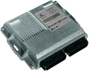
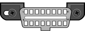
To read out, the diagnostic plug of the computer (in the picture) is connected to the OBD plug. This OBD connector can usually be found at the bottom of the dashboard near the footwell (near the pedals). The plug can also be hidden in other places in the dashboard or behind ashtrays. By connecting the plug to the readout computer, the fault codes are passed on to the computer.
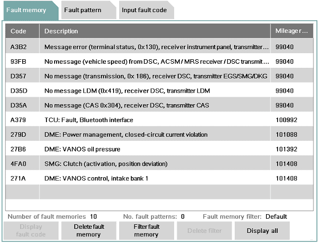
When the car is read out, the ECU will transmit a fault code to the readout computer. This error code (OBD error code) is often the same for every brand. These codes can be displayed with a reading device. The trouble code is remembered by the ECU and also stores the following information:
- When the failure occurred first and last.
- How many times the failure has returned.
- Whether it is a permanent or a (sometimes) recurring failure.
Fault codes are not always the same for every brand. Sometimes the codes are brand specific. You can often find out the meaning by looking up the error code in Google.
Extensive reading equipment links a text to this fault code. Actually, the code is then translated into a text. For example, the code P0267 will be linked to the text: “Coolant temperature sensor implausible signal; short circuit with plus.” First occurred at mileage ……km, frequency 120, occurred sporadically. Now it is clear that either the sensor has an internal defect, or the signal cable of the sensor is short-circuited with a positive cable. This has happened a total of 120 times and is not permanently present. This can mean that by moving the cables, the short circuit has occurred 120 times and then disappeared again. It is up to the mechanic to find out where the fault is.
When the fault has been rectified (eg after repairing the cable), the fault can be cleared. A code is then sent with the test equipment to the ECU, which then understands that the fault must be written from the memory. If the cable is not repaired, but only the fault is cleared, this fault will return immediately. After clearing, the first odometer reading will be the current one and the frequency will start again from 1.
Control functions and control of the engine management:
The engine management's task is to monitor or control the following functions:
- Engine speed
- Speed
- Accelerator pedal / Brake pedal / Clutch pedal position
- Ignition
- Injection
- Variable valve timing
- Variable intake manifold
- Alternator control (DF signal)
- Air mass meter signal
- throttle position
- EGR valve position
- Crankshaft / Camshaft Position
- Temperature control via the map-controlled thermostat
- knock control
- Lambda control
- Electronic coolant pump
- Tank vent
- Fuel pump (lift and high pressure)
- Cruise Control
- Crankcase ventilation heating
- Oil level control
- Turbo pressure
- Intake Manifold Pressure
- Energy management (battery charge level sensor)
- Transmission communication (withholding engine power when shifting in an automatic transmission)
- Self-diagnosis (eg for storage of fault codes)
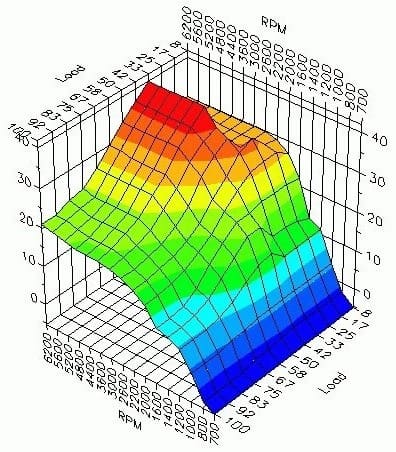
The incoming signals are all processed in a characteristic field (see the image above). The map will process the input signals (from the sensors) based on, among other things, the engine speed and load, the outside air, coolant, engine oil and exhaust gas temperatures. This data is used to determine what the output will be, i.e. how an actuator will be controlled, for example. For example, when the engine is cold, more fuel will have to be injected (cold start enrichment) to keep the engine running. This used to happen with the manual choke, but with the engine management this is all automatically controlled using the VE and AFR tables. These tables represent the filling degree and mixing ratios.
The outside temperature and coolant temperature are measured and when the engine is running, the ignition timing is determined using the knock sensors and the speed sensors determine whether the engine is running smoothly. The throttle valve will also be controlled more “open”. After a certain time has passed, the temperature in the combustion chamber will be high enough to switch to normal injection.
When the engine is in the warm-up phase as just described, it is called “Open Loop”. The feedback from the lambda sensor is then not considered. This measures a much too rich mixture (with the cold start enrichment) and would therefore actually want the engine to run leaner. But because the enrichment is necessary, the data from the lambda sensor is ignored. When the engine is at sufficient temperature, the incoming signals from the lambda sensor will be used again. This is then called “Closed Loop”. Briefly summarized: The ECU determines which signals are used and which are not.
The different attributes are shown on the page injection system described.
Adaptive Memory:
The engine management software contains a so-called “adaptive learning memory”. The actuators are controlled on the basis of the previously received data from the sensors. This takes into account some wear and contamination of the engine. In the case of wear, for example, consider a lower compression final pressure, so that the idle speed is lower than with a new engine. The engine management software will have to respond to this by adjusting the fuel trims.
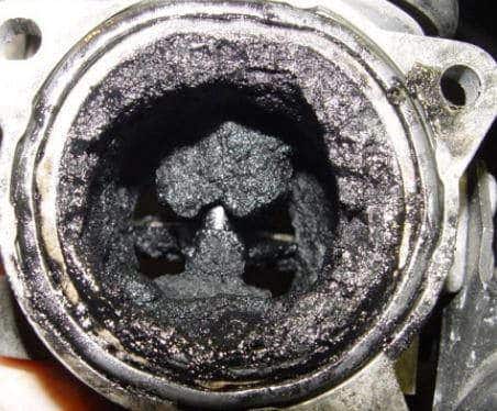
In the adaptive memory, among other things, the data of the opening and closing of the gas valve are stored. Over time, the throttle valve becomes dirty due to the influences of the EGR and the crankcase ventilation fumes. Opening and closing the valve is a bit more difficult and the valve has to open a little further in case of contamination, because otherwise the carbon residues block the airway. The regulation for an engine that is somewhat older will therefore be different than for a new engine. Without the adaptive memory, the controller would have to search for the right values every time the engine was started. With the adaptive memory, the engine management software takes this into account.
After cleaning, for example, the gas valve or EGR valve, it often has to be taught-in. Enrollment resets the adaptive memory. After teach-in, the engine management will again check and store the values of the sensors. It is therefore possible that the engine runs and shakes a little erratically after learning.
A oxygen sensor slows down as he gets older. The data does arrive in the engine management, but through the adaptive memory, the engine management takes the aging of the oxygen sensor into account. So it is important to clear the adaptation values after the oxygen sensor has been replaced.
The automatic transmission contains clutches that are actuated with oil pressure to shift gears. Older gear oil is often somewhat contaminated and thicker than new oil. The speeds and shifting moments will therefore be different with new oil than with old oil. The automatic gearbox also contains a control unit with an adaptive memory, which has adjusted the switching moments as optimally as possible over time. After the oil is changed, the shifting behavior can be very different. Think of wrong speeds to switch to lower or higher gears, or abruptly switching gears so that a thump can be felt in the drive. For this reason, the gearbox adaptation values must also be deleted after an oil change.
Often an adaptation drive must be taken after the adaptation values have been cleared. In that case, as much as possible, the vehicle must be driven at different revs and speeds, so that the system is given the opportunity to properly calculate and store the adaptation values.
The occurrence of an error code:
A sensor may be defective. The wiring or plug connection of the sensor can also become defective, disrupting the connection between the sensor and ECU. So the ECU receives wrong values from the sensor. In the past, this could affect the operation of the engine; a faulty temperature sensor could cause far too much fuel to be injected and the engine “flooded”. This chance is much smaller these days. The engine management can recognize that the value of the sensor is incorrect.
In this example the voltage profile of a temperature sensor shown. The temperature works with voltages between 0,5 and 4,5 volts. Voltages lower than 0,5 volts and higher than 4,5 volts are in the prohibited area. The voltages can be seen in the graph below. If the sensor is defective, or a cable has a short circuit with ground, a voltage of 0 volts is transmitted. This is in the forbidden area. The ECU recognizes this and stores an error code.
Not only is the error code stored, but the signal is also not used. The ECU switches to an emergency run situation; a replacement value is calculated from other data received by the ECU. The replacement value is close to the actual value, so you can drive further to the garage. Of course, it is not the intention that the malfunction is ignored, because, for example, the fuel consumption can increase considerably.
Customizing the software:
The software in the ECU can be modified with suitable equipment. And of course the knowledge, because incorrect programming can cause serious defects to the motor. Rewriting the software can be done by a software update from the manufacturer (by fixing errors discovered afterwards) or by tuning. With this, a higher power is obtained by adjusting the map in the ECU. On the page chiptuning there is more information about this.