Learning objectives and topics:
- Tuning the engine management system
- VE table
- AFR table
- Ignition Advance Table and Cold Advance
- Dwell battery correction
- Switch on ignition and start, Cranking Pulse
- Stationair
- Acceleration
- Priming pulse
- Additional enrichment
Tuning the engine management system:
The previous chapters described how the engine was prepared and what choices were made to shape the engine management system. In the embodiment it is described how the obtained data is processed in the engine management system. Entering all parameters is not yet sufficient to start the motor. There still needs to be "tuned", with which adjustments are made on the basis of measurements and experimental results.
The software setting of the motor has a major influence on the operation. Improper adjustment can cause erratic running, stalling and can even lead to engine failure. The latter can occur with a mixture that is too lean. The injection time and injection quantity depend on a number of factors:
- Rpm;
- Tax;
- Temperature.
In order to achieve a good mixture formation at all times under varying operating conditions, the ECU must be set correctly before the first engine start. The settings are made by filling in a number of tables, namely:
- The VE table for volumetric efficiency;
- The AFR table for the air/fuel ratio;
- The ignition table for the ignition timing.
The tables are entered in the TunerStudio program. Entering incorrect values may cause the motor to malfunction; system knowledge is therefore a requirement here. The following sections explain how the tables were established. The basic injection time, i.e. without enrichment, is determined by means of a number of calculations.
The specific gravity of the air (ρ) is calculated from the measured temperature of the intake air and the negative pressure (the value of the MAP sensor). It should therefore be clear that properly completed tables are necessary for the proper functioning of the engine.
VE table:
In the chapter injection system explains what the VE table is for. This section explains how the data for the VE table is determined for the Land Rover engine.
In the VE table, the percentage associated with the underpressure in relation to the speed is indicated in each cell. This percentage will be highest at the speed at which the torque is highest. After all, there the engine is most efficient because the engine fills the best. The torque and power curve of the Land Rover engine is shown in the image below.
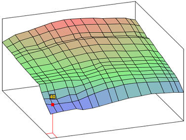
The figure shows a VE table filled in with a generator. The Y-axis indicates the pressure in the intake manifold that is registered by the MAP sensor. 100kPa is equal to 1 bar (the outside air pressure) and is the maximum pressure that prevails in the intake manifold of an atmospheric engine. The X-axis indicates the engine speed.
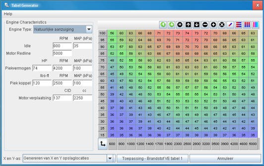
Before the engine is started for the first time, the VE table should be filled in with an estimate. The final setting of the VE table will have to take place on a test bench using a broadband lambda probe and a disabled lambda control. The program “TunerStudio” that provides the MegaSquirt with the software and the parameters has a utility that calculates the values in the VE table. However, the VE values can also be calculated using formulas. The data from the table is used to fill in the formulas.
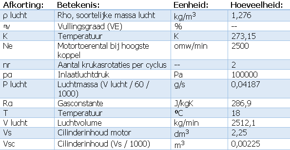
V air is determined under the same conditions as in a previous calculation; namely at the engine speed at which the torque is highest. The answer from a previous calculation is therefore taken over by the following formula.
The (under) pressure in the inlet manifold and the inlet air temperature influence the density of the air, and thus also the formula for the filling degree. The degree of filling can be determined with the known and calculated data from table 3 and this formula.

In the cell at 2500 RPM and 100 kPa in the VE table 70% can be filled. This is in the top row of the number sequence, with the throttle fully open. The calculations can be repeated a number of times to be able to fill in other numbers in the VE table. Intermediate cells can be generated by means of an interpolation function. The computer thus determines the intermediate values by means of a linear progression. This ensures that the "hill" seen in the 3D view is as smooth as possible and that there are no pits and dots in between. When the cells in the 100 kPa range between the idling and maximum speed are filled in, the torque development can be derived from this. For example, if the torque is halved at maximum speed, the VE value will also be half of the maximum value; in this case about 35%. If it is decided to fill in the cells as estimated, the entire VE table can also be filled in this way. The VE table compiled from the foregoing calculations and reasoning will be good enough to run the engine, but will certainly not be correct yet. The final setting of the VE table should be done on a test bench using a broadband oxygen sensor and disabled lambda control to avoid AFR corrections, which can lead to extended engine loads. Because no test bench is used for this project, the adjustment will be made as well as possible in the idling range and with increased speed at low load.
Getting it to idle properly is the trickiest part and is done last. It is recommended to keep the engine at an increased speed (approximately 2000 rpm) and to let the engine warm up until the engine is at operating temperature. Temperature changes then have as little influence as possible on the VE values. After the complete VE table has been corrected, the corrections for the lower temperatures (eg cold start) can be entered. This is possible in the separate setting programs such as the cold start enrichment.
The maximum speed of the motor is a factor that must be taken into account when completing the table. With a table of 16 * 16 = 256 cells, it is more accurate for the intermediate speeds to limit the maximum speed as far as possible. It makes no sense to keep the table up to 7000 rpm. to be filled in, while the maximum speed is 4500 rpm. amounts to.
When adjusting the approximately completed VE table, the current lambda value will be used to correct the percentage at the correct intake manifold pressure (MAP) and speed. This value must be obtained by adjusting the VE value to λ = 1. For example, if a mix ratio of 12,3 is measured while 14,7 is set in the AFR table, the VE value will need to be decreased until a mix ratio of 14,7 is measured. Lowering the VE value means less fuel will be injected. The mixture gets leaner.
The Innovate broadband lambda probe with external controller measures the mixture composition and passes this on to the MegaSquirt by means of a voltage between 0 and 5 volts. The software converts this voltage value into an AFR value (eg lambda = 1). After measuring and adjusting various cells in the VE table, the intermediate cells can be filled in automatically by means of interpolation. Adjusting the VE value results in a different injection strategy. The control of the injector is derived from the value that indicates how much air is present in the engine: in other words, the value in the VE table.
Unfortunately we did not have a dynamometer and it was not possible to test the bike on the road under load. Therefore, we are somewhat limited to no-load running. There is, however, a brake drum that originally served as a parking brake. This brake can be operated momentarily to load the motor. With a gear engaged (for example, fourth) and a power-assisted brake, the lambda value can be corrected at certain speeds. We correct the intermediate values by means of the interpolation function. It is possible that detonation occurs during the test. At an earlier stage, the ignition table was filled in, in which the ignition advance was entered. The desired advance may differ from the values entered in the table. When hearing light detonation sounds, the ignition should be brought forward a few degrees less (i.e. delayed). A grade or 3 is often sufficient. This can of course be adjusted again afterwards when the VE table is complete. The values of the VE table can also be shown in a 3D view. This provides insight into whether there are no major deviations, such as deviating points and potholes.
Not only can it be checked whether the values calculated by the generator are logical, but the VE table could also be partially filled in without using the generator. The motor is most efficient around the speed at which the torque is highest, where the fill rate is highest and the value in the VE table is also highest. After all, the VE table indicates the degree of filling of the engine as a percentage.
After the VE table has been completely filled in, the lambda control can be switched on again.
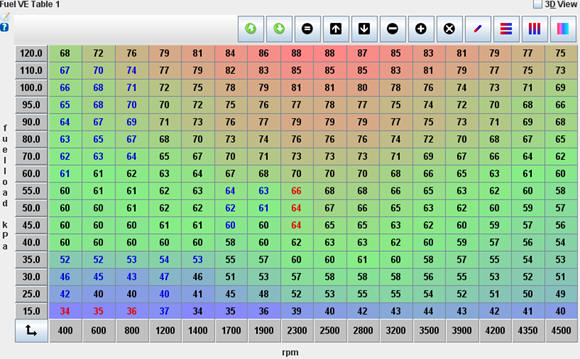
The images below show the completed VE table and the 3D view with which the Land Rover engine is functioning properly.
AFR table:
The injection system page describes the function of the AFR table, and why the impoverishment and enrichment is necessary to deliver power and drive economically. This page describes how the AFR table is set up for the Land Rover engine.
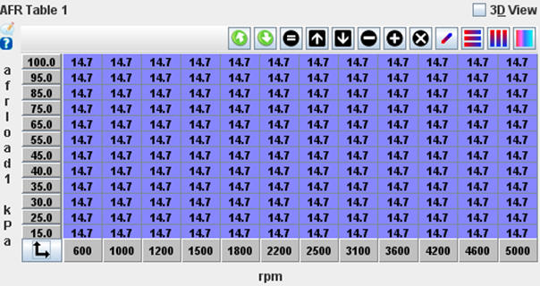
First the VE table is set, only then the AFR table is corrected. However, the AFR table must be set entirely to 14,7 in the beginning, so that the MegaSquirt will not perform a correction when the VE table is filled in (see image). Initially, a stoichiometric mixing ratio is assumed. The lambda control is also switched off. Only after setting the VE table will the AFR table be filled in and the lambda control will be switched on.
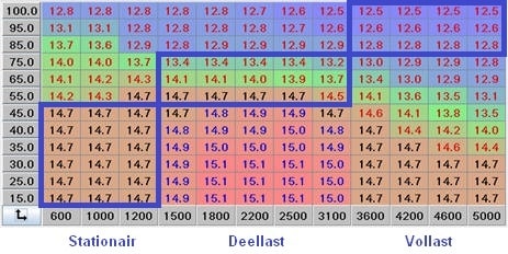
The image shows a completed AFR table, where the air/fuel ratio varies between 12,5 (rich) and 15,1 (lean). When filling in the AFR table, the mixture will be enriched in the full load area. The enrichment can be seen over the entire area between 75 and 100 kPa. The gas valve is fully open in this case. The mixture is lean during partial load and around the torque speed; the mixing ratio here is 15:1. This can be seen between 1500 and 3100 rpm. at an underpressure of 15 to 40 mbar. In this case, the throttle is only partially open. The engine is most efficient in this area.
Ignition Advance Table and Cold Advance:
On the page ignition system describes what the ignition advance means.
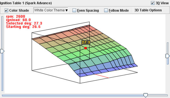
The ignition advance table is set according to the factory data of the vacuum controlled centrifugal advance. The black line indicates the mechanical advance.
The blue line represents the map arrangement. A correction is applied to avoid ending up in the partial load knocking area; the actual advance follows the red line.
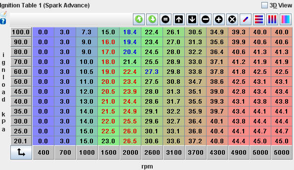
The 3D view shows that there are no abnormal values, such as potholes or hills. The table should be fairly “even” and should not have too many bumps.
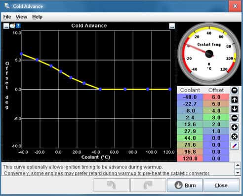
In addition to the standard settings in the ignition table, the "Cold Advance" also offers the option of bringing the ignition forward even more when the engine is cold.
When the engine is cold, more advance will have to take place because the combustion is slower. To compensate for this delay, the advance is increased by up to 6 degrees. The image shows these settings.
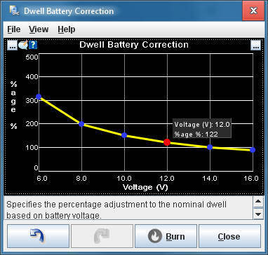
Dwell battery correction:
On the page “Actuators”, the section on the ignition system used describes the influence of the battery voltage on the charging time of the primary coil coil. The image shows the settings screen, in which the already calculated corrections are entered.
Switch on and start ignition, Cranking Pulse:
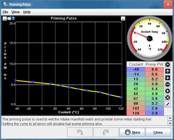
After the ignition is switched on, not only is the fuel pump energized, but the injectors are also actuated once. This is called the “priming pulse”. The gasoline injected during the priming pulse settles on the – probably – cold walls of the intake manifold. The starting process will now be easier, because the fuel injected to start with will not be lost to the aforementioned situation. The amount of fuel injected during the priming pulse depends on the engine temperature. A warm engine needs a lower priming pulse. The desired amount can be set in a chart in TunerStudio.
The starting speed is often less than half the idle speed. The so-called “Cranking Pulse” must be set in the MegaSquirt. Since no throttle is applied during start-up and the throttle thus remains in the closed position, the required air must pass through the idle control valve. It is possible to set a throttle position at which the injection is terminated. A stepper motor is used in this project. This stepper motor is therefore partially opened during starting. The position depends on the coolant temperature; more air when the engine is cold and less when the engine is warm. In addition to the air supply, the injection must also be adapted to the conditions in which the engine is started. The amount of petrol is adjusted by varying the injection time. At a coolant temperature of 25 ⁰C, the injection quantity is doubled compared to a situation where the engine is at operating temperature (around 90 ⁰C). The figure shows the curve where the injection quantity in relation to the coolant temperature can be set. A PWM of 100% is equal to the calculated amount of fuel, anything above that is additional enrichment.

Stationary:
The throttle should be fully closed when idling. The air supply during idling is completely controlled by the applied stepper motor.
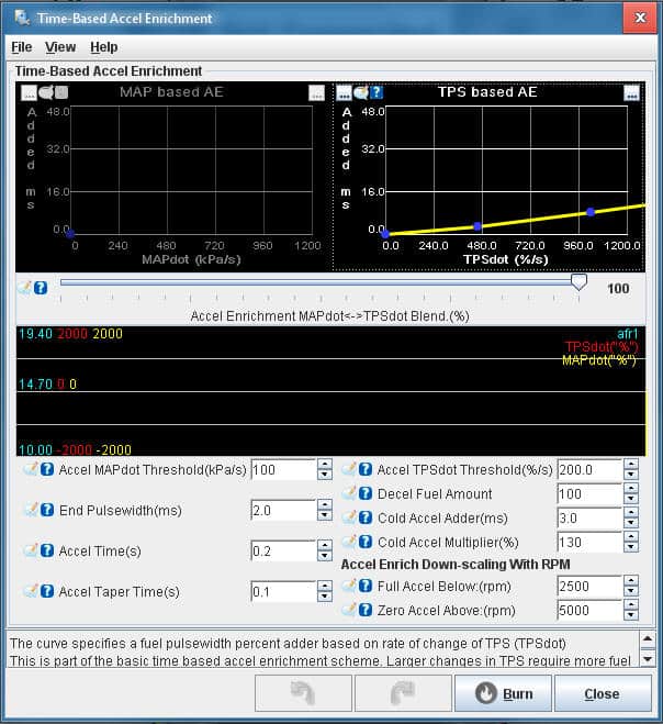
Acceleration:
Acceleration requires a richer mixture. The mixture ratio should be adjusted according to the speed at which the accelerator pedal is depressed. In the TunerStudio program, the acceleration enrichment is set with the option “Acceleration Enrichment”, abbreviated as “AE”. Setting the acceleration enrichment should only be performed when the VE table has been correctly completed.
Because the engine in this project is equipped with both a throttle position sensor and a MAP sensor, both the throttle position and the underpressure in the intake manifold can be determined. TPS dot is used for the change in throttle position. The “Dot” indicates the rate of change and is expressed as a percentage. Depending on this percentage, more fuel is injected. The injection time is extended by a few milliseconds. A TPS-Dot value of 100% indicates that the throttle has moved from closed to fully open in a 1 second period. If the opening takes place even faster, the percentage will increase. It is important to know from what value the throttle is opened; If the engine had been running at partial load for some time before accelerating, it cannot be assumed that the throttle valve was completely closed. The position of the throttle is indicated as a so-called acceleration threshold, or a “threshold”. The threshold indicates from which throttle position the throttle has been moved to the fully open position. The acceleration taper shows the transition time from the acceleration injection time to the end of the injection enrichment. This prevents the acceleration from ending too soon.
The acceleration gain setting can initially be checked with the simulator. A final adjustment will have to take place experimentally, with or without the aid of the broadband lambda probe.
Priming Pulse:
The priming pulse is a function to spray a small amount of fuel on the intake valves when the ignition is switched on. This simplifies the start-up process. When the engine is warm, the injection quantity decreases. The priming pulse is adjusted with the blue points in the curve (see image).
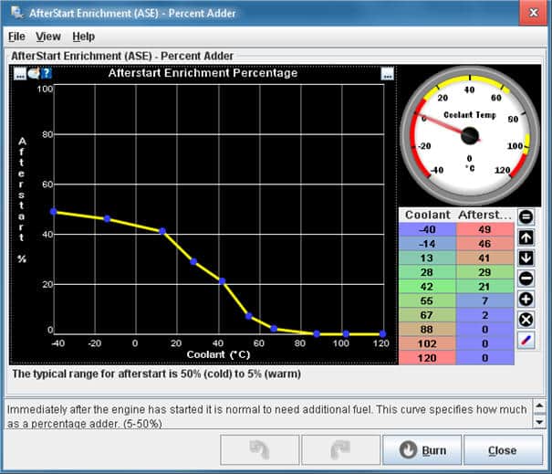
Additional enrichment:
An enrichment is applied immediately after the engine has started after starting. This is called the “AfterStart Enrichment”. The MAP is still too high because the speed is not yet high enough to provide enough vacuum. Especially when the engine is cold, enrichment takes place for a certain time until the engine starts to run according to the VE settings.
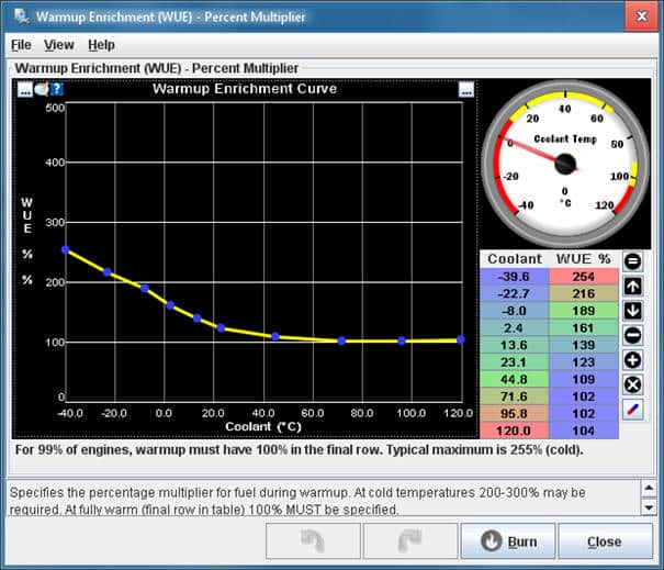
The “Warmup Enrichment” (WUE) provides an enrichment during the warm-up phase of the engine. When the engine approaches its operating temperature, the enrichment should be 0%.
Next: Free Trial.