Subjects:
- breakout box
- Read electronics schematic
- Measure with the multimeter on the breakout box
- Measure with the oscilloscope on the breakout box
breakout box:
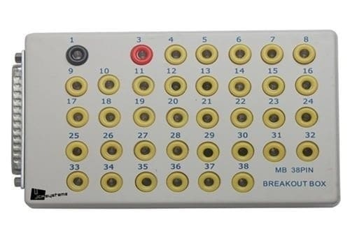
A breakout box is a tool to perform measurements. With the help of the breakout box, plugs do not have to be opened and cables do not have to be bare to perform measurements. Each wire has its own measuring point. The image below shows an example of a breakout box.
When voltages have to be measured on the control unit, this is only possible when the plug is connected. Firstly, with a disconnected plug, good measurements can never be made and secondly, the engine will not be able to run when it concerns the engine control unit. For this reason, unfortunately, the cables are sometimes pricked. By inserting the measuring pin into the wire, the voltage on this wire can be measured. However, the insulation is damaged, so a new failure will occur months or sometimes even years later due to too high a contact resistance or cable break; moisture can easily get into the cable now. This can be prevented with a breakout box. Reputable garages and well-trained specialists will therefore never prick the cables, but use a breakout box.
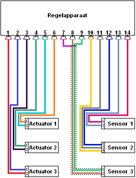
The diagram on the right shows a control unit that is connected to various sensors and actuators. There is not yet a breakout box here, but a well-functioning one engine management system.
The actuators (left) and sensors (right) have two or more wires per plug. These connections are often:
- plus (12 or 5 volts);
- pasta;
- signal or control.
In order to be able to perform measurements on the sensors and actuators, it can be checked whether there is enough space in the sensor of the component to insert the pins of the multimeter or the oscilloscope. Often the plugs are waterproof and you cannot reach the contacts without damaging the cable. It is of course not wise to make the cable bare or to pierce the cable! In order to be able to perform good measurements, a breakout box can be placed between the control unit and the sensors / actuators. This can be seen in the diagram below.
The control unit plug in the diagram on the right is located on the breakout box. The breakout box plug is in turn connected to the control unit. In this way, the sensors and actuators are still connected to the control unit, so the entire system will function without interference. In the breakout box there is a connection between the wires.
The breakout box contains all connection points; in the figure below, these connections are shown as circles above the numbers. The numbers of these connections correspond to the pin numbers of the control unit. Each wire in the plug of the control unit therefore has its own measuring point in the breakout box. Resistors are visible between the wires and the terminals. These resistors are often around 500 Ohms and serve to protect the measurement that may be performed incorrectly. Without these resistors, the chance that the control unit will blow up is considerably higher.
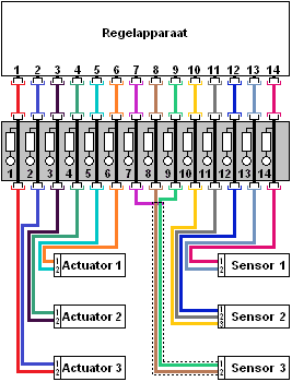
Example of a measurement: When the signal from sensor 1 is to be measured, one is interested in the voltages that are on pin numbers 1 and 2 of the sensor plug (these numbers are written in small near the wires).
The pink wire is on pin 1 and the blue wire is connected to pin 2. When the plug is insulated, the voltage should be measured further down, i.e. at the control unit or the breakout box. The pink and blue wires go to pins 13 and 14 of the breakout box. The voltages measured here on pins 13 and 14 are therefore the same as if measurements were made directly at the plug of the control unit, or directly at the plug of the sensor.
The example above shows an elongated breakout box with 20 connections. In reality, breakout boxes are often square or rectangular, and sometimes have more than 100 connections. It is also often possible to connect multiple plugs to a breakout box. In that case, pay close attention to the coding. If, for example, the coolant temperature sensor has to be measured, then it must first be checked to which control unit and therefore which plug this sensor is connected (eg T60). The breakout box also contains other meanings, for example T45 and T32; these are different plugs. The correct plug can be found in the circuit diagram.
Read electronics schematic:
To clarify the following story with the measurements, all terms, indications and abbreviations of the relevant electrical scheme are explained. The scheme below is of the “waterfall” type. This means that the plus(es) come from above and the mass is at the bottom. The current actually flows from top to bottom. Terminal 30 is the constant plus, terminal 15 is the switched plus. A power supply is generated here when the ignition of the car is on. Terminal 31 is the ground of the battery.
The diagram below is part of the fuel system with a fuel pressure sensor and the fuel lift pump with the float element:
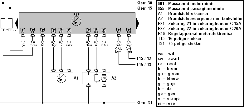
Fuses F21 and F22 are located in fuse holder C. This fuse holder is located in the dashboard, left on the driver's side. The control unit, (named R16) is the engine control unit. This is located behind the engine compartment, near the wiper mechanism. The diagram shows two black arrows to the left and right of the control unit; these indicate that the control unit is larger than the one shown in the picture. It can also be seen that the pin numbers have no logical order; starting at pins 2 and 3, followed by 26, 38 and 39. The pin numbers on the Control Unit connector do increase evenly, starting at pin 1 through pin 75. These Control Unit terminals have all wires to and from the sensors and actuators connected.
Each wire has its own pin number and color. The explanation of the colors can be found in the legend. The wire ro/sw means that it is a red wire with a black line (not the other way around).
Furthermore, the components such as the sensor and the pump are indicated with a code (A1 and A2). At A2 there are two wires to ground; one from the variable resistance of the tank float and one from the electric motor of the pump.
On the right side of the diagram you can also see the CAN bus wires with the CAN high and the CAN low. These wires run to plug T15, connections 12 and 13. The plug T15 is located in a different place in the car; this location can be found in the workshop documentation. In this case it concerns the plug on the Gateway. This scheme is used in the following examples, where measurements are taken with the multimeter and the oscilloscope.
See also the page: Read electrical diagrams.
Measure with the multimeter on the breakout box:
The schedule is reproduced below. In this case we want to check the supply voltage. In the diagram it can be read that on plug T94 of the engine control unit R16, pin 3 shows the constant plus of the battery:
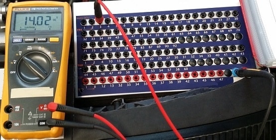
In the picture below, a measurement is taken on the breakout box with the multimeter. The plus pin (red) of the multimeter is connected to terminal 3 of connector T94 (T94 is shown in orange). The mass is measured via the blue connection; this is the central mass of the breakout box itself.
In the diagram it can be read that the control unit is connected to ground via the wire and pin 21. If the negative pin is kept on pin 21 and the voltage is 0 volts, while the multimeter reads 14,02 volts via the central ground, it is possible that the ground wire between pin 21 and the ground point on the body is broken. That would explain if there is a trouble code stored about an interruption in the ground, or if the control unit cannot be switched on.
Measure with the oscilloscope on the breakout box:
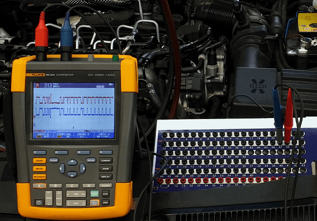
With the oscilloscope the voltage can be measured in relation to a time course. This can be useful, for example, when measuring CAN bus signals. We will do this below. The diagram shows that the CAN bus wires are on pin 67 and pin 68 of connector T94 on the control unit R16:
The two measuring pins of the oscilloscope are therefore connected to pin numbers 67 and 68 of the breakout box. The masses of these test probes are connected to any ground point on the car. After the scope is set correctly, the following image will be visible:
With the help of these examples, a good picture can be formed of how the breakout box can be applied in practice. The voltages can be measured with the multimeter as well as the oscilloscope. The disadvantage is that the currents cannot be measured.