Subjects:
- The start of the project
- Motor
- Gear box
- Inspect, replace and adjust engine parts
- Mounting the motor on a wheeled frame
- Cooling
- Dashboard and electrical installation
- Fuel pump and tank
- Let the engine function in a classic setup
The start of the project:
After it was decided to provide an engine with a MegaSquirt engine management system, a suitable engine type was considered. Standard conversion kits with manuals were not interesting. The objective was to use an engine that met the following conditions:
- no previous conversion projects of this engine should be known;
- four-cylinder petrol engine;
- not yet equipped with an injection and electronic ignition system;
- the ability to load the engine.
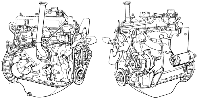
Engine:
The search resulted in an engine from a Land Rover (series 2A) from the early 70s. This 2,25 liter four-cylinder petrol engine with three main bearings was originally equipped with a carburetor and mechanical distributor ignition. The combination of this Land Rover engine and the original gearbox was decisive for the choice; a transmission brake is mounted on the output shaft of the gearbox. The transmission brake, which actually serves as a parking brake, makes it possible to apply the load to the engine while it is running by applying this brake.
The engine probably hadn't worked for decades. Of course, it must be reliable enough to run on the engine management system. It was therefore necessary to thoroughly inspect and test the engine first. The following objectives were made:
- Inspect, replace and adjust engine parts;
- Mount the engine on a wheeled frame;
- Let the engine function in the classic setup;
- Install components for the engine management system;
- Assemble and prepare MegaSquirt ECU;
- Operate the engine on the engine management system.

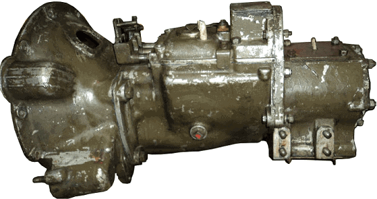
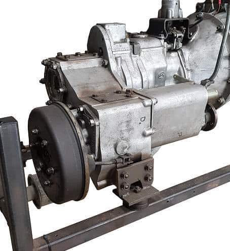
Gear box:
The gearbox comes from a Land Rover from the army. The green color already betrays it. In order to form a whole – as original as possible – with the engine at a later stage, the green paint has been removed. The transmission brake is not yet present in the photo; this was later mounted on the output shaft, according to the manufacturer's instructions.
To inspect, replace and adjust engine parts:
At the start of the project it was unclear whether the engine provided was suitable for use. Little was known about the engine block, only that the engine had been standing still for years. It was unclear whether internal parts were damaged or even – possibly irreparably – defective. In the latter case, replacing the engine with another one was the only way to resume the project.
In order not to come to the conclusion at a later stage that the engine would be unusable, it was decided to disassemble and overhaul the engine. Wear patterns of the parts were checked and compared to factory specifications. Parts for which the measurements were within these tolerances have been replaced. Parts that were rejected have been replaced. The purpose for which the engine will be used has been taken into account; the engine should be built at the lowest possible cost in order to be sufficiently reliable for the implementation of the project and its use as an educational tool.
The engine is attached to the mounting bracket on the suspension points of the gearbox housing. The motor can be turned in different positions. This means that both the cylinder head and the sump pan are optimally accessible for disassembly work. For the correct functioning of the engine it is important to take precautions to ensure a good compression final pressure. If the pressure of one or more cylinders is too low, this results in a malfunctioning, faltering engine. In that case, adjustment with the newly installed ignition and the injection system is difficult, if not impossible.
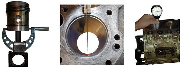
One of the first check points are the pistons and cylinder walls. In order to exercise a good control, the pistons had to be disassembled from the engine block. After dismantling the cylinder head and the sump, the pistons could be removed. The pistons have been checked for ovality and visible signs of wear. The piston rings have also been checked for wear. Worn piston rings can cause loss of compression and oil consumption; both consequences should be prevented by this check. In addition to an optical check, the clearance between the piston ring grooves and the piston ring was also measured.
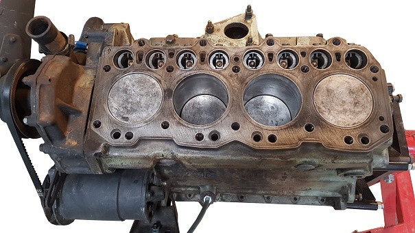
The image below shows a measurement where the piston is measured with a micrometer. In addition to the ovality, the distance between the piston and the cylinder wall can also be determined. A gap that is too large means excessive wear. For the project this would mean that other oversized pistons may have to be installed. After the four pistons were visually and geometrically assessed, it was determined that there was no excessive wear.
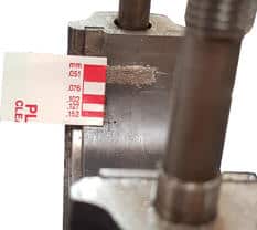
After replacing piston rings, the lock clearance must be measured and, if necessary, adjusted to prevent the piston ring from breaking (as a result of too small or too large clearance) and to counteract compression loss (leak losses due to too much clearance). The piston ring is placed in the cylinder where the diameter is smallest. The lock play is measured with a feeler gauge. This measurement is shown in the picture. The piston rings of cylinder 1 were replaced due to their bad condition and had to be filed a millimeter smaller; in the assembled state the ends touched each other.
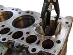
The wear of the cylinder liners is measured with a suitable measuring object. The movement of the pointer shows the degree of wear. The picture shows the cylinder measurement of cylinder 4. The cylinder diameter will have increased, especially on the side where the slideway force occurs. The cylinder walls may show some wear, but the wear must fall within the tolerances. The measurement results showed that there was a permissible wear on the cylinder walls. An optical check of the cylinder liners revealed that some parts of the walls were smooth. The honing quarries were no longer or barely present.
The honing grooves, a kind of small scratches, ensure that there is always a small oil film between the piston ring and the cylinder wall. This oil film has the main task of lubrication, but also serves as a seal and thus helps to achieve the compression final pressure. New honing grooves have been made in all four cylinder liners using a honing stone intended for this purpose. The image shows this operation. An attempt has been made to apply the honing grooves as crosswise as possible, at an angle of 45 degrees.
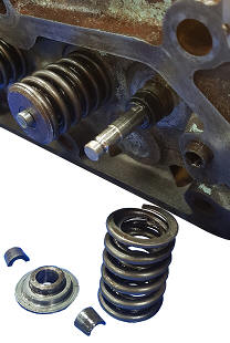
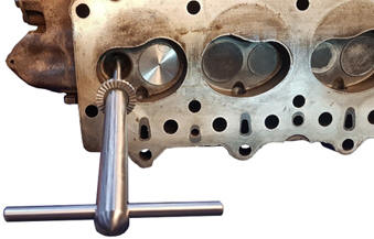
The valves seal the combustion space above the piston. Leakage along the valve seat will result in a loss of compression; something that should be avoided. In order to be able to check the condition of the valves and the valve seat, all valves must first be removed from the cylinder head. The picture shows a disassembled valve spring of the inlet valve of cylinder 1. The valve discs of the valves of cylinder 1 were so affected that it was decided to replace both.
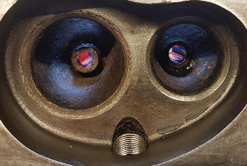
After the disassembly, a number of valve seats appeared to have been eaten into / affected. The picture below shows the valve seats of cylinder 1. With a high degree of probability, the engine would not have functioned properly if it had not been checked. Merely regrinding the new valves would be insufficient, so it was decided to mill the valve seats.
With a valve seat cutter, a small amount of material is removed, so that the valve seat is smooth again. The shank of the cutter is slid into the valve guide (see figure below). This ensures that the router can be placed straight on the seat. During the machining process, two different angles have been taken into account in which milling has to be done. The valves of cylinders 1 and 2 were most affected. For completeness, all eight valve seats have been machined. After milling, the valves are sanded in with a special abrasive to ensure the best possible seal.
A dial indicator measures the crankshaft axial play of the crankshaft with three main bearings and two axial bearings. If there is too much axial play, an axial bearing of a larger size can be fitted if there is no mechanical defect. The measurement shown in the picture showed that the axial clearance was OK.
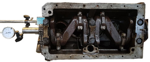
The space between the crankshaft and connecting rod journal bearings, in other words: the crankshaft radial play, is measured with plastigage (see picture). Plastigage is a special plastic wire that permanently deforms after compression. After mounting the bearing cap or connecting rod, the plastigage will leave a mark. The width of the print indicates how much clearance there is between the plain bearing and the crankshaft.
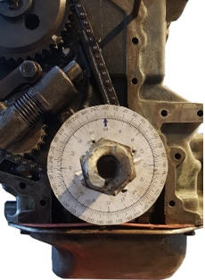
The timing chain transfers the movement from the crankshaft to the camshaft. After mounting the pistons, crankshaft and cylinder head, the timing chain must be readjusted after mounting. Due to the lack of adjustment and markings, the adjustment had to be determined on the basis of the asymmetric valve diagram. The angle at which the intake and exhaust valves open and close can be determined by means of a degree disc on the crankshaft (see figure). The distribution parts such as the sprockets, chain, guide and tensioner have been checked for optical wear. This was okay.
All parts are tightened according to the prescribed tightening torques. Because the engine has been disassembled, checks must be carried out after a few kilometers driven. However, this is not possible because the engine is not installed in a vehicle. It has therefore been decided to carry out the checks prescribed by Land Rover after 24 hours of operation.
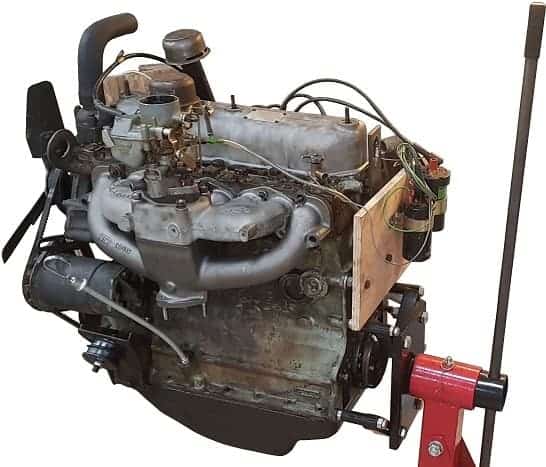
Mounting the motor on a wheeled frame:
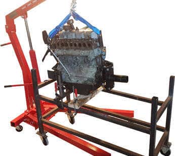
The aim was to use the engine as an educational tool, running on an engine management system. The engine is not placed in a car. To ensure a safe and reliable setup, it was decided to place the motor on a suitable motor frame. It is intended that the engine is mounted on the engine frame in the original positions of the engine mounts. Because there are no ready-made conversion kits, the supports had to be made to measure.
In the build-up phase, the choice had to be made how the engine should be built. The engine management system must be adjusted under increased engine load. Because a transmission brake is present on the original gearbox, it was decided to also mount the gearbox on the engine frame. By operating this transmission brake it is possible to run the engine under load for a short time.
Editing and adapting the existing engine mounts has made it possible to reliably connect the engine to the frame. The engine frame also offers the possibility to attach a dashboard, on which, among other things, the operation can be realized. The image shows the moment when the motor is suspended above the frame and ready to be mounted.
The engine mounts on the timing side are made of tubular steel and U-profiles. A motor rubber provides the damping. At the bottom, two tubes are mounted on top of each other to mount the combination of the engine and gearbox as horizontally as possible on the frame. The supports are attached to the engine block and frame by means of M8 and M12 threaded rods, bolts and nuts.
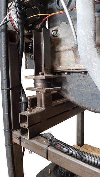
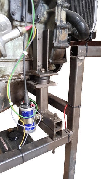
Such a gearbox support is made on both sides of the gearbox, with which it rests on the frame.
After the engine and gearbox were mounted on the frame in a safe and reliable manner, the construction of the engine could be resumed. After the assembly of adjustable and adjustable parts, such as the carburettor and the ignition, these were adjusted according to the factory values.
Other components that enable the engine to function are also mounted on the frame, such as the radiator, dashboard with controls and fuel tank. These components are described in the following sections.
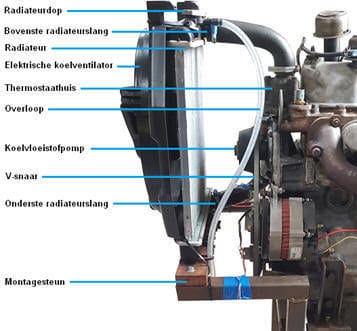
Cooling:
The cooling is realized in original condition by a large radiator and a metal cooling fan mounted on the water pump. Because the engine is not installed in a vehicle, but on a wheeled frame, it is important to use suitable aftermarket components. The metal cooling fan was replaced by an electrically driven cooling fan with plastic fan blades. Not only is the plastic version a lot safer because the engine is made suitable for educational purposes (think of personal safety when taking measurements), but it is also more suitable for heating up the radiator and the engine block more quickly. The electric cooling fan can be switched on and off with a button on the dashboard. This gives the opportunity to quickly warm up the engine, because there is little possibility to put a mechanical load on it. When the engine is warmed up, there is more of a “closed loop” where the data from the lambda probe is used to control the fuel injection. For example, when the engine is cold – in “open loop” – additional enrichment takes place: when a larger quantity of fuel (λ < 1) is injected, the fuel correction by the lambda sensor is undesirable.
The figure shows an overview of the components of the installed cooling system. The original radiator was not present. Because the size and weight of this were not suitable for mounting on the engine frame, a smaller after-market radiator was chosen. The diameters of the connections of the upper and lower radiator hoses correspond to the original.
The upper and lower radiator hoses are custom made with silicone hoses and fittings. The electric cooling fan is secured to a mounting bracket. The upper radiator hose protects the radiator from tipping over. An overpressure cap (0,9 bar) protects the cooling system against too high pressures. When the pressure rises too high, the valve in the radiator cap opens against the force and coolant flows through the overflow to a container.
It had to be determined experimentally whether the radiator had a sufficiently high flow rate and whether the cooling fan had sufficient capacity to dissipate the heat. During the first test phase, the system was found to be in order.
Dashboard and electrical installation:
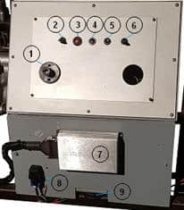
A dashboard is mounted on the frame, which contains indicator lights, switches, the MegaSquirt ECU, various relays and cable bundles. The dashboard is used to monitor and operate the engine functions.
The image shows the dashboard. Number 1 in the figure indicates the location of the ground switch; a key breaks the connection to the battery's ground. Since it is not necessary to supply voltage to the switched-off motor, it is safer to interrupt ground when the motor is left unattended. Number 2 indicates the switch for the cooling fan. Numbers 3 and 4 the indicator lights for the alternator (D+), number 5 the start button and number 6 the ignition switch (terminal 15). There is a fuse box on the back of the dashboard. The MegaSquirt is mounted on the bottom panel and is indicated by number 7. Number 8 indicates the fuel pump relay. The dashboard also offers the possibility to mount a breakout box on which students can take measurements. This makes it possible to measure the sensor values and actuator controls with the oscilloscope.
The original starter relay controls the starter motor; with a small start button, pin 86 is grounded, causing a control current to flow. The control current provides a magnetic field, causing a main current to flow between terminals 30 and 87; the starter motor is supplied with this main current until the starter button is released.
The retrofitted alternator provides the charging voltage and current to the battery. A control lamp indicates whether the alternator is charging properly. The lambda probe, injectors and ignition coil receive a power supply from the fuse box. The information transfer and switch-on and switch-off commands of the MegaSquirt are provided via other signal and ground wires.
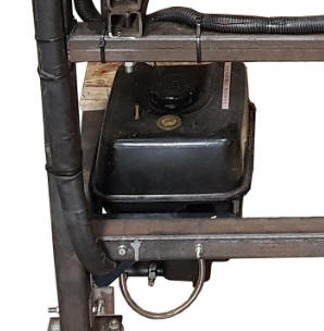
Fuel pump and tank.
The mechanical fuel pump in the classic arrangement is no longer used when the components of the engine management system are installed, because the operating pressure is too low (200 mbar). The required fuel pressure for MPI injectors controlled by the MegaSquirt ECU is 3 bar. A standard electronic fuel pump from a passenger car is sufficient. Due to the limited space, a compact unit was chosen, in which the fuel tank, pump and filter are located in one housing. A metal frame makes it possible to mount the unit to the motor frame. At a later stage of the project, the fuel hoses that form the connection between the fuel pump and the injectors in the intake manifold will be installed.
The feed wires from the fuel pump are routed via a cable duct to the instrument panel, the installation of which has already been described. The positive wire of the pump is energized by the MegaSquirt via a relay.
Operate the engine in a classic setup.
Before installing the components for the engine management system, the engine was initially made functional in the classic setup, i.e. with carburettor and distributor ignition. Chapter 5.2 describes the work that took place to mount the engine and auxiliary components on the engine frame. In the first test phase, where the engine was started in the classic setup, checks could be made under the following conditions:
- Cold start;
- idling;
- Increased speed, increased load;
- Extended running at operating temperature.
During the above checks, it appeared that a number of repairs still had to be made before the engine was reliable enough for the conversion.
- After the first engine start it turned out that the seal in the coolant pump was no longer in order; the coolant was leaking past the bearing from the engine block. Replacing the coolant pump was enough to fix the problem.
- Another problem was the stalling when the engine reached operating temperature. The ignition went out, making it impossible to start the engine. The problem was in the distributor and could be solved easily.
- Over time, an oil leak formed between the engine and the gearbox. The leak is probably from the crankshaft seal. This leakage will be resolved after completion of the project.
After the engine was found to be in order in the classic setup, the electronics could be continued.
Next: Sensors.