Preface: If there is a suspicion that there is a malfunction in the CAN bus, a diagnosis can be made by, among other things, measuring the voltage levels on the wires. The content of the CAN bus message is initially not important. We can perform measurements on the CAN bus wires with both the multimeter and the oscilloscope. The measurements with the multimeter do have a limitation; when measuring the voltages, only an average value is indicated. The multimeter is sufficient to a limited extent when measuring an interruption or short circuit. The oscilloscope is required to measure the voltage levels and assess whether the signal has a clean path.
How a CAN bus system works and how the structure of the messages is established is explained on the page CAN bus. This page focuses on measuring the CAN bus with the oscilloscope and the multimeter and possible faults with causes are described.
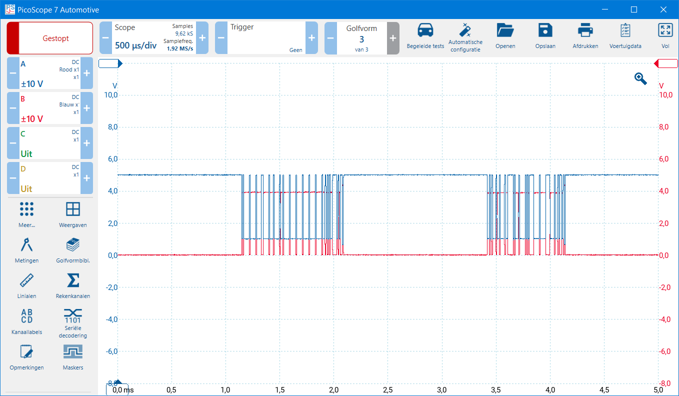
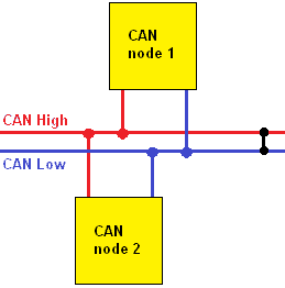
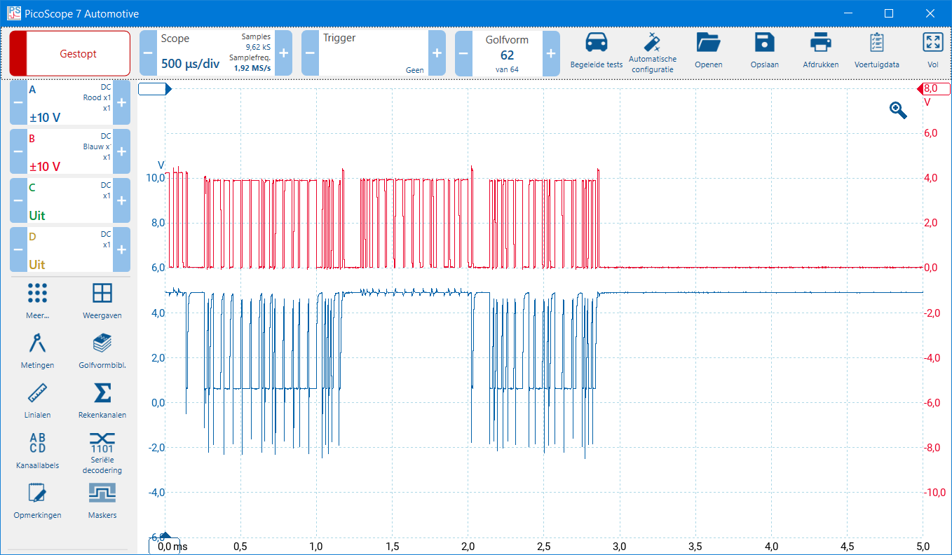
Diagnosis CAN bus signals low / medium speed: With a two-channel oscilloscope, the CAN-high and CAN-low can be measured simultaneously with respect to ground. The two scope images below show the CAN bus signal of the comfort bus. This is also called the “low speed” or the “medium speed”. We often find this network in the comfort electronics, for example the door electronics, BCM, air conditioning control unit and the instrument panel. The voltages are as follows:
CAN-low: idle 0 volts, active 4 volts;
CAN-high: idle 5 volts, active 1 volt.
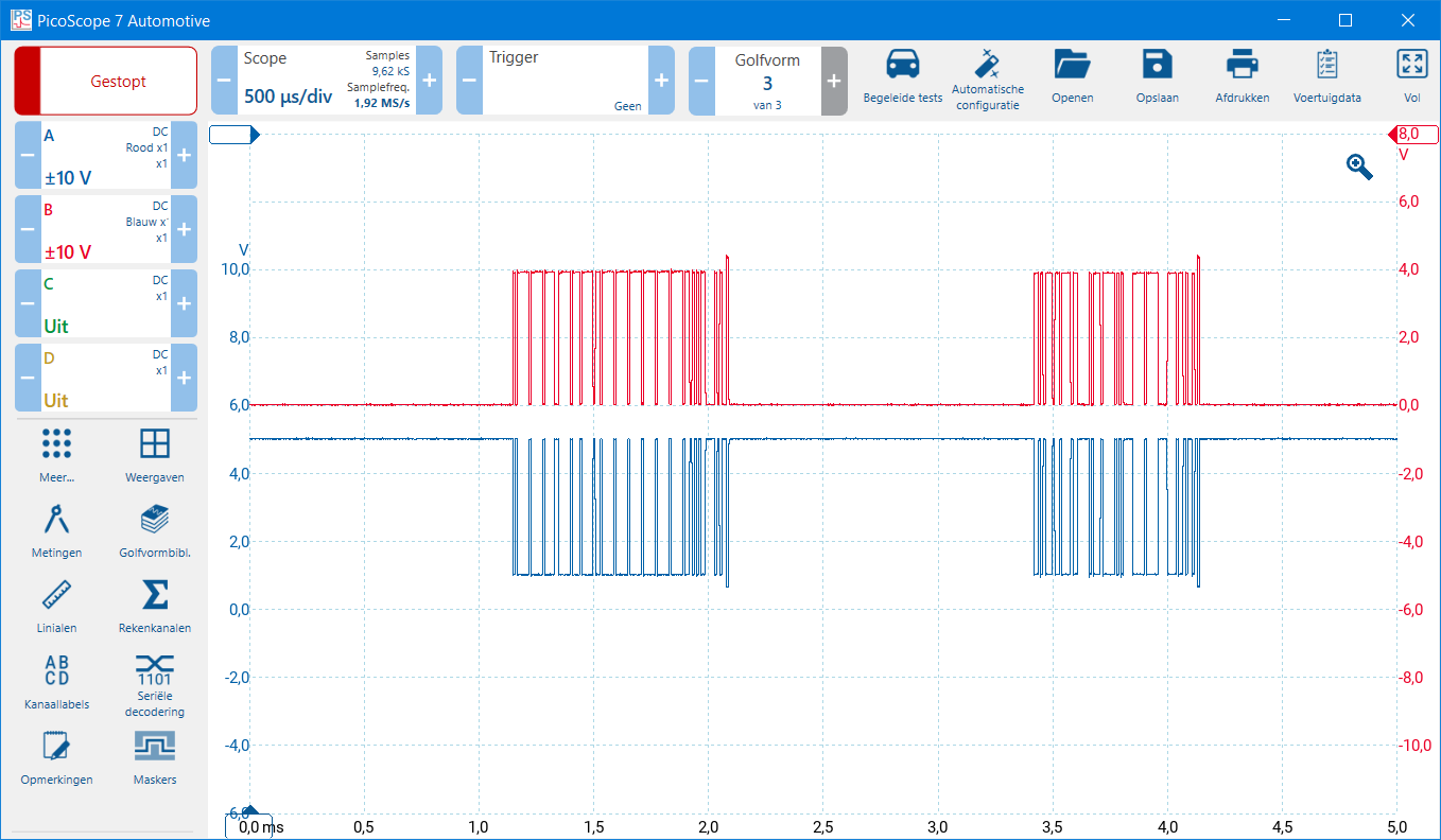
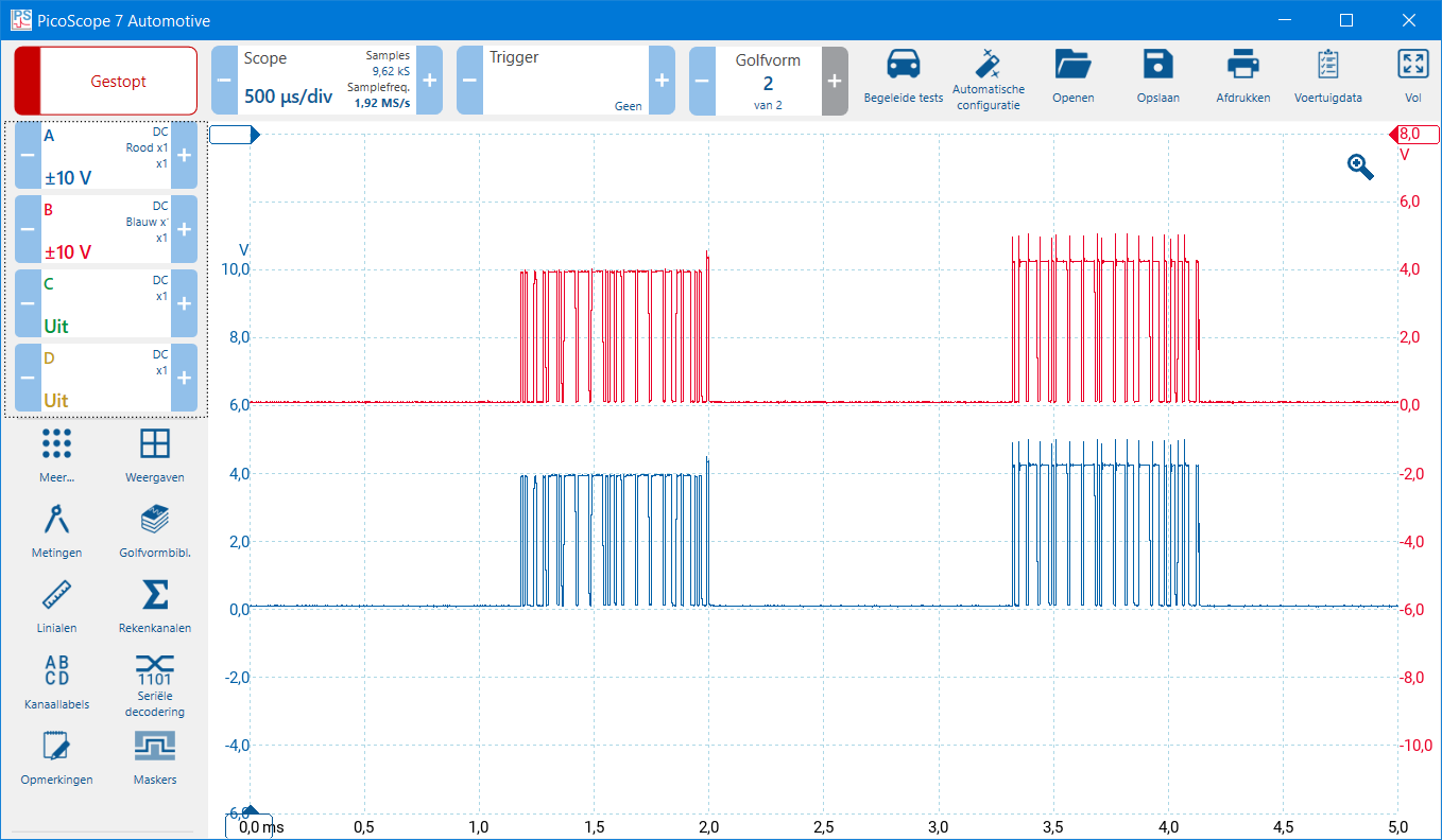
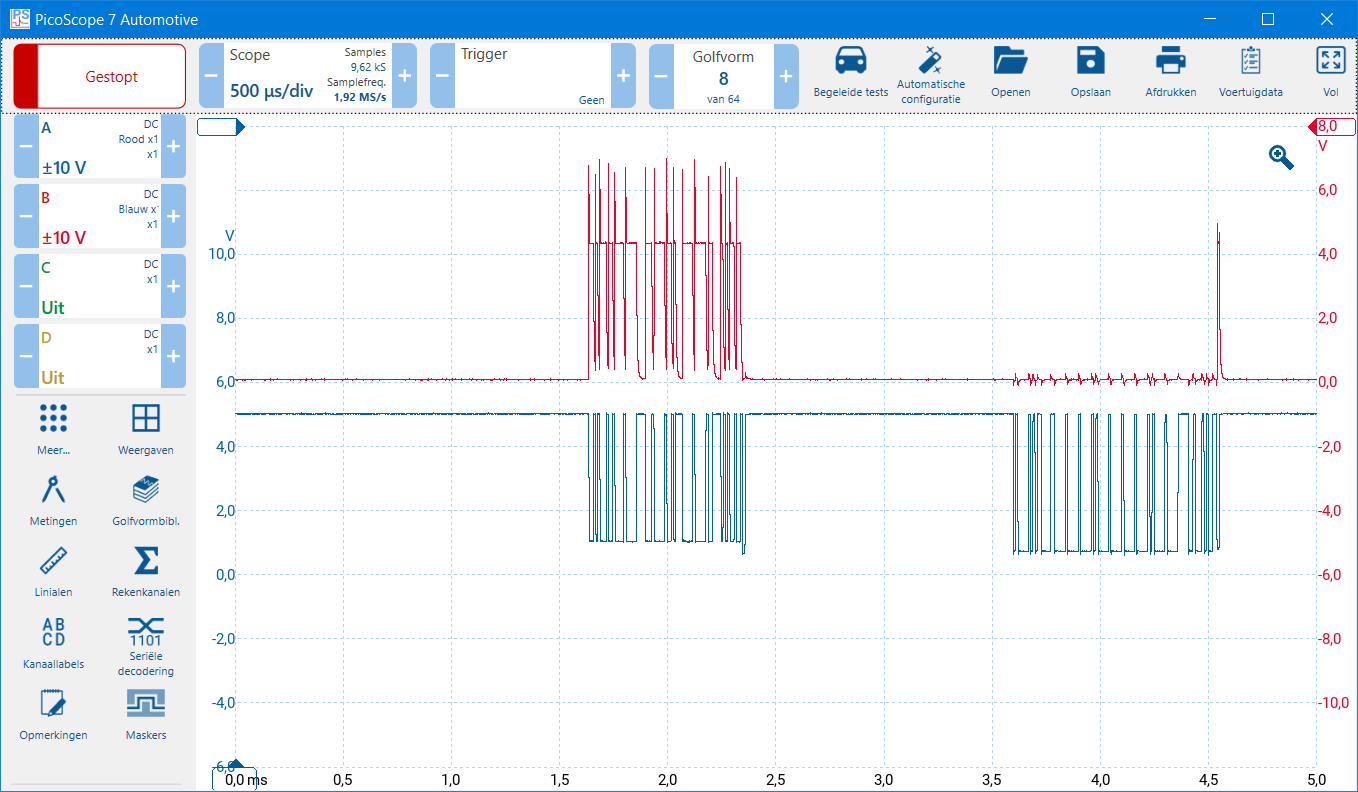
When we set the zero lines of both measurement channels to the same height of the Y-axes, the signals overlap. It is therefore advisable to move the Y-axis of the CAN-low upwards for reading. In the second image below, the zero lines have been changed in height, so that the voltage curve of CAN high and low can be compared with each other.
Please note: the low and medium speed CAN networks are often not equipped with terminating resistors, unlike the high speed CAN network. The measurements taken on a fault are therefore also different. This section shows the possible disruptions of the low and medium speed network, and the next section shows the high speed network.
CAN-high and CAN-low (low speed) with the zero lines at the same height of the Y-axis
The same measurement of CAN high and CAN low with a shifted Y axis
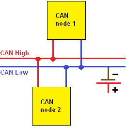
CAN high shorted to ground: There is a ground short in the CAN high. If the insulation is damaged, the wiring can make contact with the body, or in an ECU a short circuit is made to ground.
In the measurement below, we see a constant voltage line on channel B that is 0 volts.
CAN high shorted to ground
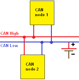
CAN-low shorted to ground: There is a ground closure in the CAN-low. If the insulation is damaged, the wiring can make contact with the body, or in an ECU a short circuit is made to ground.
In the measurement below, we see a constant voltage line on channel A that is 0 volts.
CAN-low shorted to ground
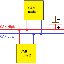
CAN high shorted to plus: In the CAN-high there is a positive circuit. If the insulation of several wires in a wiring harness is damaged, the wiring can make contact with each other, or in an ECU a short circuit is made with positive.
In the two measurements below we see:
Channel overrange: the voltage range of channel B (red) must be increased;
On channel B we see (in the 20 V range) a constant voltage line that is equal to the battery voltage.
CAN high shorted to positive (1). Outside the measuring range.
CAN high shorted to plus (2). Measuring range adjusted.
CAN-low shorted to plus: There is a positive circuit in the CAN-low. If the insulation of several wires in a wiring harness is damaged, the wiring can make contact with each other, or in an ECU a short circuit is made with positive.
In the two measurements below we see:
Channel overrange: the voltage range of channel A (blue) must be increased;
On channel A we see (in the range 20 V) a constant voltage line that is equal to the battery voltage.
CAN-low shorted to plus (1). Out of measuring range.
CAN-low shorted to plus (2). Measuring range adjusted.
CAN-high shorted with CAN-low: The CAN low changes to the CAN high voltage ramp when they connect to each other. A short circuit between CAN high and CAN low can occur in the wiring, where the insulation of both CAN bus wires is worn through, or due to a defect in the printed circuit board of an ECU.
In the picture below we see the two channel measurement where CAN high and low are shorted together.
Short circuit between CAN high and CAN low
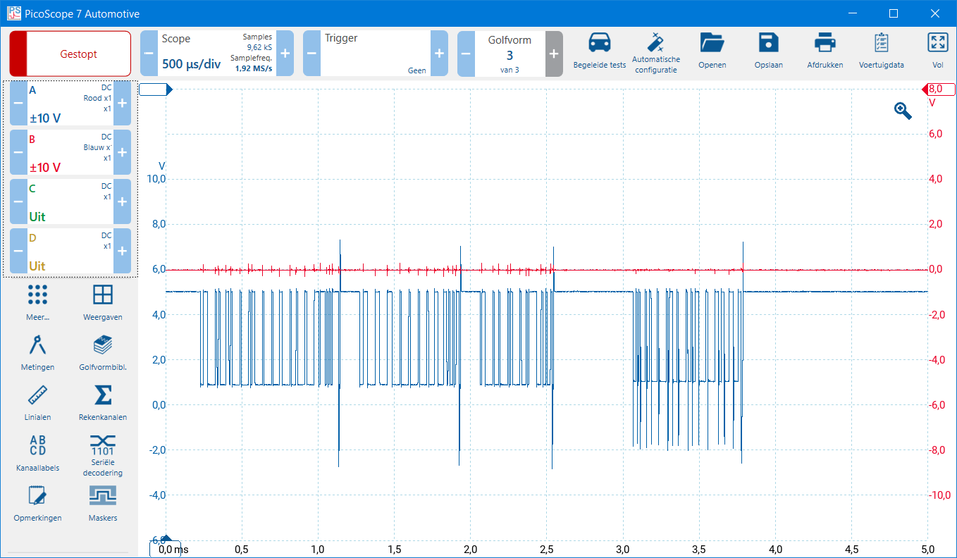
On CAN-high, communication is occasionally lost: Communication with one control unit in CAN-high is interrupted. This control unit no longer sends and receives data via the CAN-high, but the CAN-low still functions. As a result, communication and reading are still possible.
When the plug of the relevant control unit is disconnected, the CAN-low data is also lost and there is no longer a visible difference between CAN-high and CAN-low.
In the image below we see that the CAN-high remains recessive at one point, while data is sent on the CAN-low.
Communication occasionally drops out in CAN-high
On CAN-low the communication is occasionally lost: Communication with one control unit in the CAN-low is interrupted. This control unit no longer sends and receives data via the CAN-low, but the CAN-high still functions. As a result, communication and reading are still possible.
When the plug of the relevant control unit is disconnected, the CAN-high data is also lost and there is no longer a visible difference between CAN-high and CAN-low.
In the image below we see that the CAN-low remains recessive at one point, while data is sent at the CAN-high.
Communication is occasionally lost in CAN-low
Diagnosis CAN bus signals high speed: The ECUs for which a high communication speed is of great importance are equipped with a high-speed CAN network. This includes, for example, the ECU of the combustion engine, automatic transmission, ABS/ESP/EBS and the airbags. A high-speed network is always equipped with terminating resistors. Faults in the wiring and ECUs therefore also cause a different voltage profile, which can sometimes make it more difficult to diagnose than with a comfort network. As always, a trouble-free situation is first displayed before we proceed to failures.
The voltages of a high speed network are as follows:
CAN-high: idle 2,5 volts, active 3,5;
CAN-low: idle 2,5 volts, active 1,5 volts.
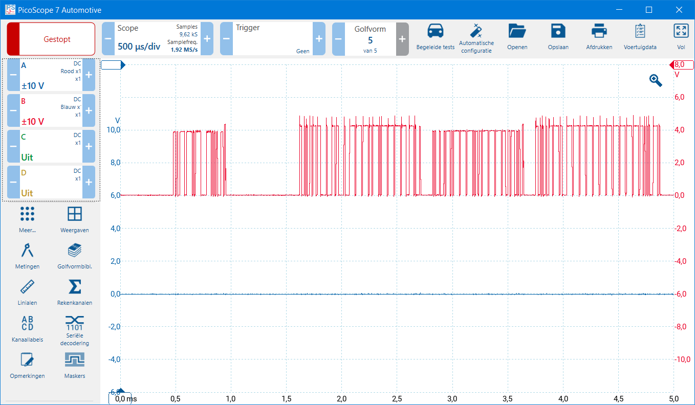
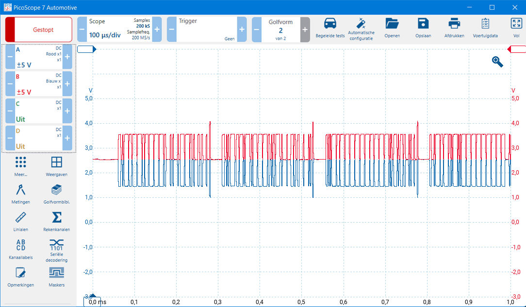
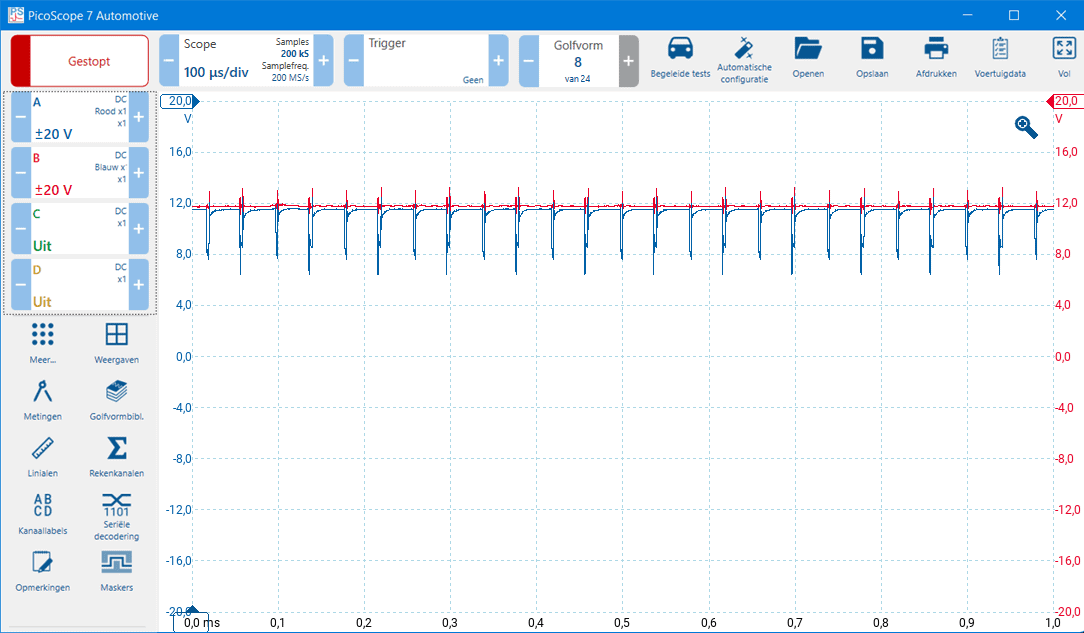
When CAN high and low are both 2,5 volts, the bus is recessive (at rest). When the CAN high rises and CAN low falls, the bus becomes dominant and a bit is formed. The image below shows a screenshot of a correct high speed CAN bus signal.
When such a signal is measured and a lot of noise is visible, it is advisable to remove the battery charger from the vehicle and connect the oscilloscope to the ground of the vehicle (the Automotive scopes have a " ground” connection on the back) and the signal can be made purer with the sample frequency. The sample rate smoothes the signal, so if it deviates too far from the standard value, the CAN signal may distort too much.
For clarity, in the image below, CAN-high is red and CAN-low is blue.
CAN-high and CAN-low (high speed) with the zero lines at the same height of the Y-axis
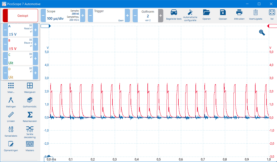
CAN high shorted to ground: There is a ground short in the CAN high. If the insulation is damaged, the wiring can make contact with the body, or in an ECU a short circuit is made to ground.
In the measurement below you can see that CAN-high (red) is exactly 0 volts, because it has a short circuit to ground. CAN-low (blue) is slightly above the zero line. When zooming in on this signal this would become even clearer. Because CAN-high is exactly 0 volts and CAN-low is a few tenths of a volt higher, we can conclude that CAN-high has a short circuit with ground.
CAN high shorted to ground
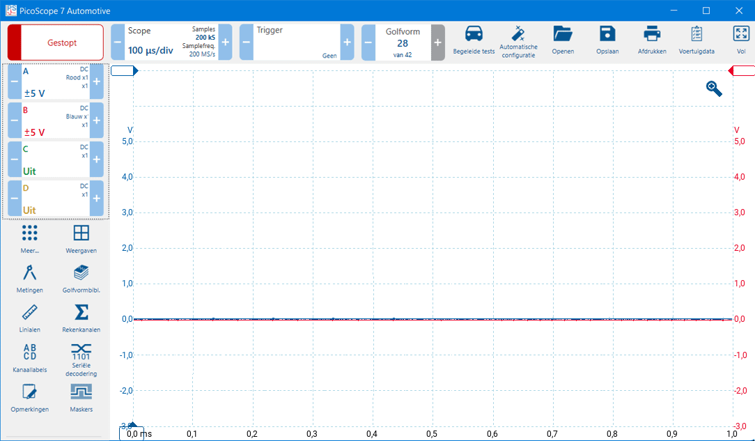
CAN-low shorted to ground: There is a ground closure in the CAN-low. If the insulation is damaged, the wiring can make contact with the body, or in an ECU a short circuit is made to ground.
In the measurement below we see that CAN-low is 0 volts. Although some noise is visible, we can ignore that. CAN-low is short-circuited to ground. We see the CAN-high voltage line keep rising, but that is not enough to start communication. The scope image also shows that CAN-low is always a lower voltage than CAN-high (red is always slightly higher than blue), which means we can assume that CAN-low is short-circuited to ground.
CAN-low shorted to ground
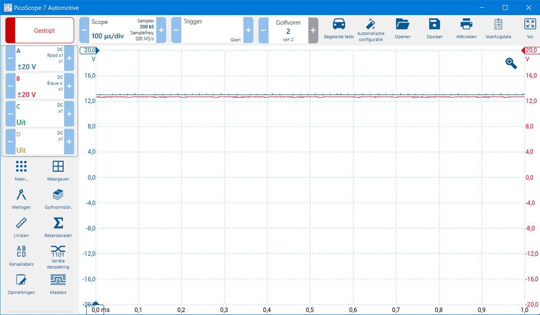
CAN high shorted to plus: In the CAN-high there is a positive circuit. If the insulation of several wires in a wiring harness is damaged, the wiring can make contact with each other, or in an ECU a short circuit is made with positive.
In the image below we see a phenomenon that resembles the situation in which CAN-low was short-circuited to ground. CAN-high (red) has risen to the on-board voltage of around 12 volts. CAN-low (blue) has also increased in voltage and is still trying to communicate by lowering the signal. Because no communication is established, the negative voltage peaks continue to repeat.
CAN high shorted to positive
CAN-low shorted to plus: There is a positive circuit in the CAN-low. If the insulation of several wires in a wiring harness is damaged, the wiring can make contact with each other, or in an ECU a short circuit is made with positive.
In the measurement below we see that CAN-high and CAN-low are around 12 volts. However, the voltage of CAN-low is around 200 mV higher than CAN-high. CAN-low has lifted CAN-high along with it. This shows that CAN-low is short-circuited with the plus.
CAN-low shorted to positive
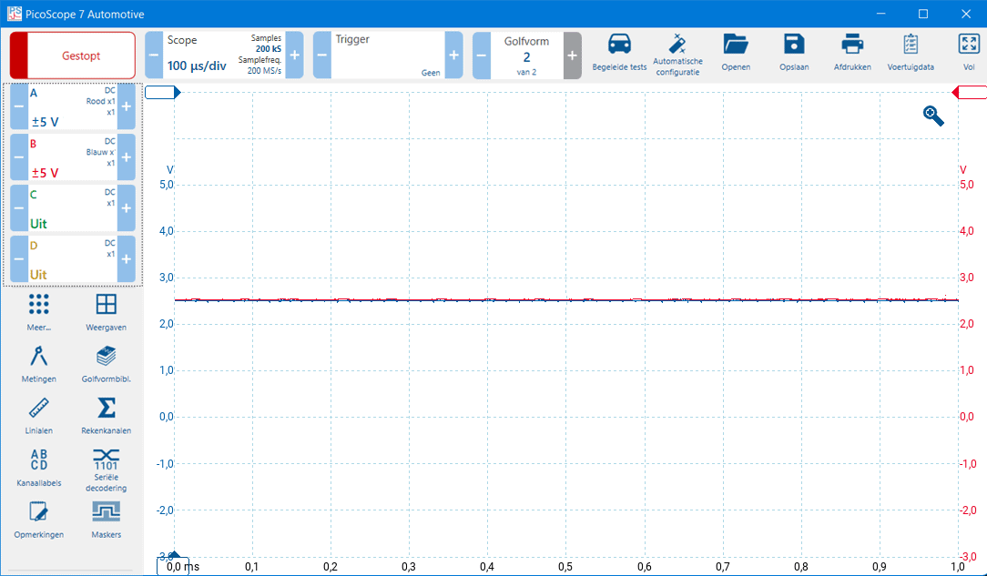
CAN-high shorted with CAN-low: The CAN low changes to the CAN high voltage ramp when they connect to each other. A short circuit between CAN high and CAN low can occur in the wiring, where the insulation of both CAN bus wires is worn through, or due to a defect in the printed circuit board of an ECU.
In the image below we see the two-channel measurement where CAN-high and CAN-low are short-circuited with each other. The voltage on both channels is 2,5 volts.
CAN-high and CAN-low shorted together
Diagnosis with the multimeter: Measuring CAN bus voltage levels with the multimeter is unwise. The multimeter displays average values when voltages fluctuate frequently, so that it is not possible to make a good diagnosis. The oscilloscope must be used to measure the voltages.
We can use the multimeter to measure the resistances of (only) a high-speed CAN network with terminating resistors. The measurements below show the ohmic resistance in three different situations: a correctly functioning system, an open wire and a short circuit between CAN-high and CAN-low. In a low/medium (comfort) network, terminating resistors are rarely used, and these measurements cannot be performed.
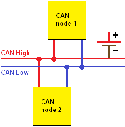
Interference-free: On the page CAN-bus it is described that there are two terminating resistors in the network. The terminating resistors both have a resistance of 120 ohms. In a fail-safe system, we will measure a 60 ohm replacement resistance between CAN-high and CAN-low.
Note: we can only measure this if the power supply of all control units is switched off!
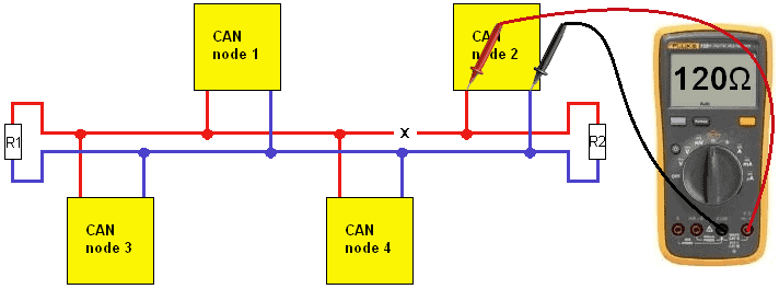
Interruption: In the event of an interruption in a CAN-high or CAN-low wire, we no longer measure the replacement resistance of 60 ohms. In the picture we are only measuring the value of resistor R2 (120 ohms).
Short circuit: In the situation where the CAN bus wires connect to each other (ie are shorted to each other), we measure a resistance value of approximately 0 ohms.
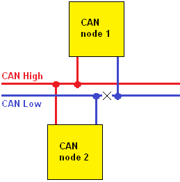
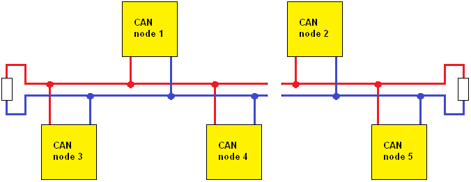
At the next fault, both CAN wires are interrupted. There will now be a lot of interference (noise) on the bus. Nodes 1, 3 and 4 can communicate with each other provided the interference and reflection is too great, causing the messages to distort. Similarly, node 2 and 5 can communicate with each other subject to the same problem.
Some CAN networks also function when one wire is interrupted. Error codes will be stored and the driver will be informed with warning lamps by messages from various systems. These are the networks equipped with a Fault Tolerant CAN transceiver. Depending on the transceiver used, different types of errors can occur without loss of communication between the nodes. These CAN transceivers can also function normally with the aforementioned faults with the short circuits to plus and ground (of course with various error messages).