Subjects:
- Interior fan
- Control of the interior fan by means of a series resistor
- Duty cycle controlled interior fan
booster:
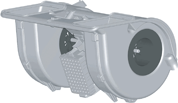
The image below shows an interior fan. This component is also called a heater motor or blower.
In the middle of the blower are the blades that blow the ventilation air into the interior. The ventilation air is drawn in at the side of the engine and is blown through the above oval channels through the heater radiator or the evaporator of the air conditioning (which are mounted directly after the interior fan in the heater housing).
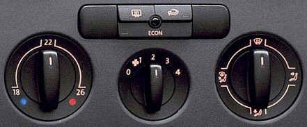
The images below show manual control panel (left) and automatic (right). The automatic control has the advantage that the fan speed, outlet temperature, demisting and recirculation are automatically set to the current conditions.

Control of the interior fan by means of a series resistor:
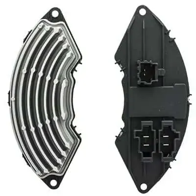
The passenger compartment fan must of course be supplied with voltage in order to work. With a voltage of 12 volts, the fan will run at maximum speed. This corresponds to position 4 where the knob is turned to (or the maximum value on the digital display of the automatically controlled ventilation). When positions 1, 2, or 3 on the control switch Worden selected , the interior fan slow down. The voltage must then be reduced. The series resistor ensures this. The three images below show different heater resistors.
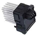


The heater resistance gets very hot; that's why it's in a duct through which air is blown. It is often located near the interior fan, or even in the same housing. The passing air cools the heater resistance.
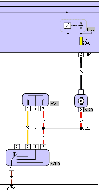
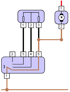
The interior fan schematic shows the following components:
- K55: passenger compartment fan relay;
- F3: fuse 20 A;
- M28: interior fan;
- R28: series resistor;
- S28b: Four position switch.
The plug codes and indications can also be seen:
- 10P, 2: plug on the electronics box, position 2
- X28: wire connection;
- G29: ground point.
The abbreviations of the wire colors are as follows:
- sw/rt: black/red;
- rt/bl: red/blue;
- ws: white;
- ge: yellow;
- br: brown.
The positive wire of the passenger compartment fan is connected to the relay by means of a fuse. The relay is energized when the ignition is turned on. This means that the passenger compartment fan always receives a plus when the ignition is switched on. The current goes through the series resistor and the switch to ground. The interior fan is therefore ground-connected.
The speed of the interior fan is determined by which, and how many resistors the current passes.
Below are three situations in which the switch switches the passenger compartment fan to ground.
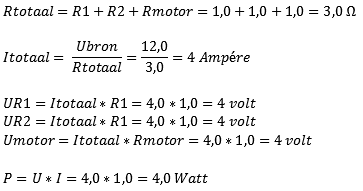
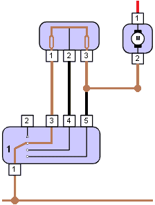
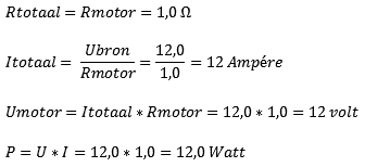
As of 1: The switch is in position 1. The current flows through terminal 3 of the heater resistor through two resistors in series. The two resistors provide a total voltage drop of 8 volts at an on-board voltage of 12 volts. The formula below shows that the passenger compartment fan operates at a voltage of 4 volts in this position.
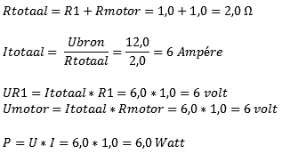
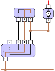
As of 2: When the switch is in position 2, the current only flows through one resistor. As a result, the formula is slightly different. We omit the value of R2. In this case there is less voltage drop and the passenger compartment fan runs at a higher voltage and current. He will spin harder.
As of 3: In this position the heater resistance is not used. The current leaves the motor and goes directly to the switch. This switches the blower directly to ground. It therefore runs on the hardest setting. The formula below takes into account the internal resistance of the electric motor. The voltage across the electric motor is now 12 volts.
Possible defects in the ventilation control with heater resistance:
- Fan only works in the highest position:
as shown in the upper diagram, the heater resistance in position 3 is not used. In the event of a defect in this component, this will not affect the highest setting. The fan can only be switched off or on the highest speed. This complaint is typical of a defective heater resistor. - Fan does not work in position 1, but does in position 2 and 3:
there may be a defect in the resistor or the connection of one of the internal resistors. In the above diagram, the resistor above terminal 1 could be defective in that case. This is easy to check with an ohmmeter; the resistance between pin 1 and 2 of the heater resistor should be approximately 1 to 1,5 ohms. If the resistance is infinite (OL or 1.), there is an internal interruption. - Fan not working at all:
check if the plus and ground are in order. In the schematic, the electric motor is connected to ground. When the ignition is on, at least 12 volts should be measured on the plus side of the engine. If you do not have a ground, check whether the switch still functions properly by checking the resistance between pin 1 and 5 (without plugs connected) with a resistance measurement when the switch is in position 3. The resistance must be less than 1 ohm.
As indicated in a previous paragraph, a heater resistor can be found in or on a heater duct through which the air is blown to the ventilation grilles, or it is mounted on the housing of the fan. If necessary, consult a repair manual to determine its location.
Duty cycle controlled interior fan:
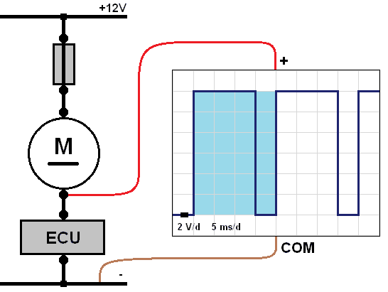
Modern ventilation systems are increasingly equipped with a duty-cycle controlled interior fan. The advantage of this control is that there is no loss, as is the case with the heater resistance. With a duty-cycle controlled interior fan, the ECU (the control unit) always switches the electric motor on and off. We can measure this with a oscilloscope.
The image below left shows both sides of the switching part of the heater motor. This component is mounted on the heater motor. Inside the housing there is a switching transistor that is controlled by the ECU. The switching transistor provides the electric motor with a power supply or ground. The transistor becomes very warm during use. The cooling fins transfer heat to the air flow that the fan moves.
The image on the right shows the scope image in which the period time (blue) is displayed.
- Switched off when the voltage on the ground side is 12 volts during this period. The electric motor has not consumed the voltage.
- Switched on when the voltage on the ground side is 0 volts during this period. At that moment the electric motor has used the 12 volts to run.
The on time is 25% of the total time, so the passenger compartment fan runs at a low speed. The longer the electric motor is grounded, the faster the fan will spin. If the ECU puts it completely to ground, it will run at maximum speed. On the page duty cycle and PWM control You will find more information about different control methods and signal processing.
Possible defects of the duty-cycle controlled system:
- ECU input not OK, think of the control unit that contains the buttons and switches. This may have been performed with LIN bus-communication. Check if communication is taking place.
- Power supply (plus or ground) of the ECU not OK. The ECU does not turn on.
- Fan power supply not OK. Check whether the fan is connected to plus or to ground and measure this. In the above diagram, the electric motor is connected to ground, so with the ignition switched on, 12 volts must be measured at the input of the motor at all times.
- Defective switching section. Check the wiring first; Are the power supply and ground on the switching section OK? Is there communication with the ECU? The ECU is often located behind the control buttons. If all measurements are correct, but the switching part does not control the electric motor, there is a chance that the switching part with transistor needs to be replaced.