Subjects:
- Operation
- Turbo hole
- twin-turbo
- tri-turbo
- Twin scroll turbo
- Variable geometry turbo
- dump valve
- wastegate
- Intercooler
- Compressor characteristic (surge & chokeline)
- Combination turbo and compressor
- Electronic turbo
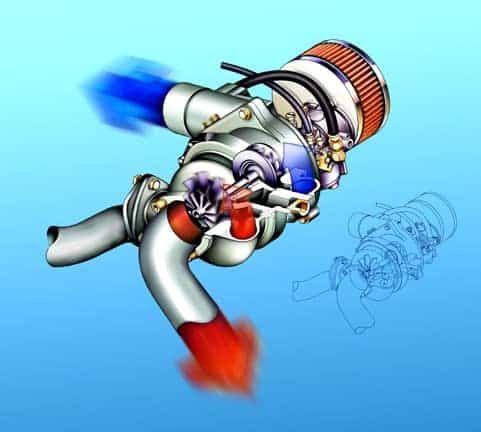
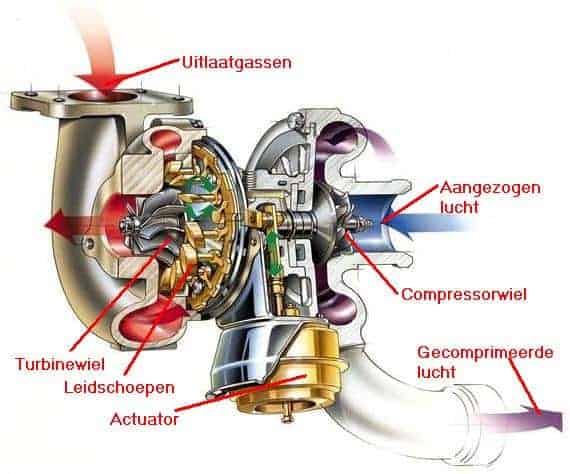
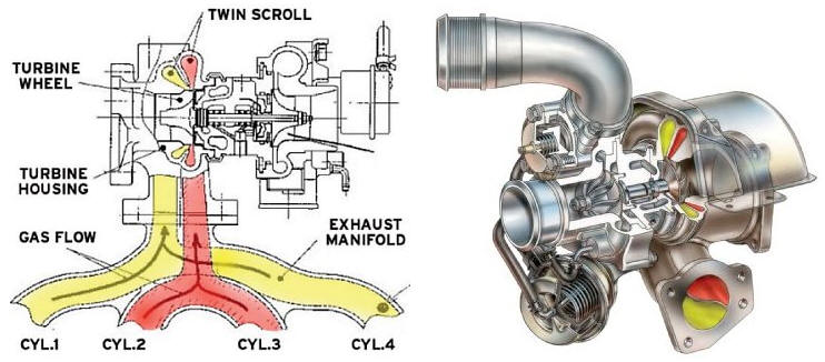
Operation:
The exhaust gases coming out of the cylinders are fed from the exhaust manifold to the turbo. The exhaust gas pressure causes the turbine wheel to rotate (the red gases). The exhaust gases then leave the turbo via the same turbine wheel to the exhaust. The compressor wheel is driven by means of a shaft (the blue gases). The compressor wheel draws in the air from the side (where the air filter is shown), and supplies it under pressure (via the blue arrow) via the turbo hose to the intercooler. The intercooler cools the compressed air (cooler air makes the engine perform better). The air then enters the intake manifold.
With the use of a turbo, more air enters the cylinders during the intake stroke than with a naturally aspirated engine, where all is sucked in because the piston moves downwards. By supplying more air to the cylinders in this way and adding more fuel to them, a higher power will be available.
Turbo pressure is measured by the boost pressure sensor. The turbo pressure is adjusted on the basis of the signal that this sensor sends to the ECU.
The turbo is mounted as close as possible to the exhaust manifold. Sometimes the manifold and the turbo are designed as one unit. The turbo must be mounted as close as possible to the cylinder head, because the speed of the exhaust gases decreases as little as possible and as little pressure as possible is lost.
Turbo hole:
Older turbos often suffer from the infamous turbo lag. The turbo works on the exhaust gases of the engine. If the accelerator pedal is pressed all the way to the bottom in one go, the engine needs a lot of supplied air from a low speed at once, but at that moment the turbo still has to start from the exhaust gases that are released. The turbo still does not supply enough pressure. Only when the engine has reached a higher speed does the turbo start properly. Usually this happens around 2000 rpm and can be felt because the car accelerates harder.
This turbo lag is seen as a major disadvantage. As a result, many people are also in favor of a mechanical compressor. This works constantly, because it is directly driven by the crankshaft and therefore always rotates at the same speed as the engine. A compressor will supply pressure from idle speed when accelerating. The turbos that are built in cars today are less affected by this, partly thanks to the variable turbo.
Twin turbo:
The addition 'twin-turbo' indicates the presence of two turbos. These 2 turbos can be located next to each other on 1 cylinder row, or 1 turbo per cylinder row. This gives the driver the benefit of greater torque at low speeds, better performance in the high speed range and a smoother engine character. At low speeds the air is then supplied to the engine by a small turbo and at higher speeds the larger turbo becomes functional. The larger turbo has a larger turbo lag, because it needs more air to get started, but this is then canceled out by the small turbo.
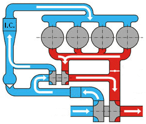
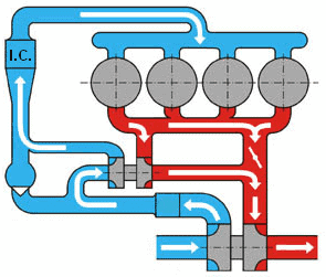
The four images below describe the situations in which the turbos both work, or when only one of the two works. The four circles are the cylinders, the red and blue parts are the exhaust gases and intake air. The intercooler is marked with “IC”.
Low engine speed and low engine load:
At speeds below 1800rpm there is a small volume flow of the exhaust gas. With the small volume, the use of the small turbo is possible. The valve between the exhaust manifold and the large turbo is closed. The exhaust gas is therefore only transferred from the small to the large turbo. The large turbo is thus already brought up to speed. There is talk of a series connection, because both turbos are used.
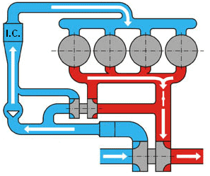
Mid engine speed and moderate load:
Between 1800 and 3000rpm the valve opens between the exhaust manifold and the large turbo. Currently, both turbos are powered directly by exhaust gases from the engine. Here too there is a series connection, because both turbos are used.
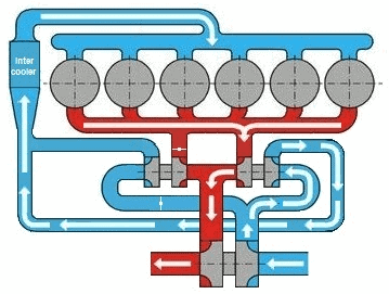
High engine speed and high load:
Above 3000rpm, the volume flow of the exhaust gas becomes too large for the small turbo. The turbo is switched off in order not to pass the so-called “chokeline” (see the chapter on compressor characteristics further down the page). The wastegate of the small turbo is opened, so that all exhaust gas that is fed to the turbo is led past the turbo. The exhaust gas then does not reach the compressor wheel.
The large turbo is fully supplied with exhaust gas. The valve remains open, so that the large turbo can make a high speed and thus move a lot of intake air to the intake manifold.
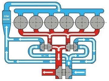
Tri Turbo:
Nowadays, "tri-turbo" engines are also made. Three turbos are mounted on these engines, so that a maximum filling degree can be achieved in every speed range. BMW applies the tri-turbo technology with the M550d, among others. The two small turbos use variable geometry, making them suitable for both low and high revs. Depending on the speed, the turbo is adjusted for better response. The large turbo uses a wastegate.
Two situations are described below in which it is indicated which turbo is in operation at what time.
Low engine speed and low load:
Only one of the two small turbos is powered. Due to the size of the turbo, it is spooled up quickly. The small turbo feeds the exhaust gas to the large turbo. The big turbo is already started with this.
Medium and high engine speed and load:
Both small turbos are powered. The two small turbos power the large turbo. This achieves the maximum boost pressure at all medium and high speeds.
Twin scroll turbo:
When multiple exhaust gases come together in the exhaust manifold, interference problems can arise; the pressure waves interfere with each other. With a Twin-scroll turbo, the exhaust gases are separated from each other, guided into the turbo in two channels. The exhaust gases from cylinders 1 and 2 therefore do not come together in the intake manifold, but hit the turbine wheel independently of each other. Applying a Twin-scroll turbo results in a faster throttle response and a higher efficiency. The image below shows that the exhaust gases from cylinders 1 and 4 come together, and the exhaust gases from 2 and 3 together.
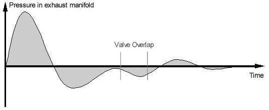
With a conventional turbo, the exhaust gases come into contact with each other in the exhaust manifold. We call this “interference”. The image below shows the pressure pulses generated in the exhaust manifold of one cylinder.
Because we are dealing with valve overlap (the intake and exhaust valves are both open during the change from exhaust stroke to intake stroke), negative pressures also arise (lower than atmospheric pressure). With valve overlap, the exhaust gases help to draw fresh air into the combustion chamber and expel the remaining exhaust gas. The combustion comb is thus supplied with more oxygen, so that the volumetric efficiency increases.
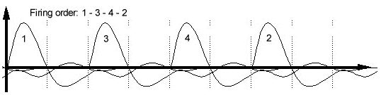
If we look at the exhaust manifold pressures of a four-cylinder engine, we see a lot of interference. Each positive pulse is reduced by the negative pressure due to the valve overlap. This is at the disadvantage of the turbo lag (reaction time to coil)
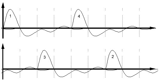
The use of the twin-scroll turbo improves the response time, because the exhaust gases from cylinders 1+4 and 2+3 are separated. The pulses are, because they are not affected by negative pulses at that moment, a lot stronger. The constructor can therefore also increase the valve overlap time to achieve even higher volumetric efficiency.
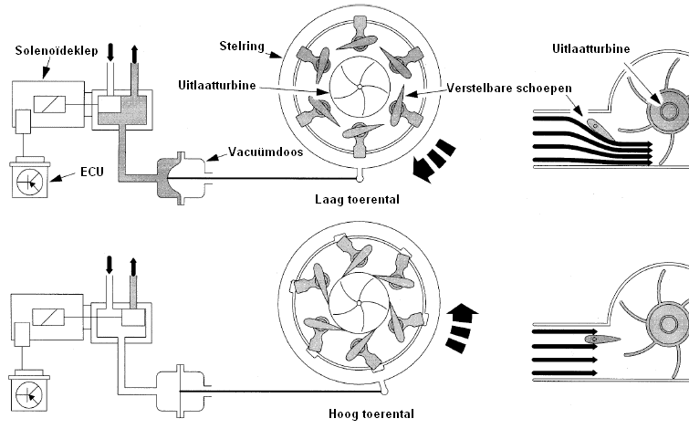
Variable geometry turbo:
A turbo with a wastegate suffers from the turbo lag; only when the engine is running a certain number of revolutions, the turbo is supplied with sufficient exhaust gases to be able to come into operation. A variable geometry turbo has no wastegate, but has adjustable blades in the exhaust duct. These blades can be adjusted by turning an adjusting ring. This adjusting ring is turned by means of a vacuum. The required amount of vacuum is provided by a solenoid valve (solenoid valve) based on the engine load and the engine speed, which is controlled by the ECU.
The airflow can be directed by adjusting the blades. Due to a change in the airflow, the turbo can already run at a higher speed at low speeds, i.e. also lower exhaust gas pressures. Due to the position of the blades, the amount of exhaust gas that can flow in is limited. In order to be able to run at higher speeds, the vanes will be adjusted inwards at a higher engine speed. A high filling pressure can be obtained at both low and high speeds. As a result, the operation of the turbo is optimal over a large speed range, because the engine will already be supplied with the same boost pressure at a low speed as at a higher speed.
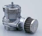
dump valve:
The dump valve is also called a “blow-off valve”. The dump valve is mounted on a turbo hose, where the air is fed from the turbo to the inlet side of the engine. When accelerated, the turbo of a passenger car can reach 200.000 rotations per minute. At that speed, the maximum charge pressure is reached. When the accelerator pedal is released all at once, there is an abundance of air pressure on the intake side of the engine, but the throttle is closed.
Without a dump valve, there is a back pressure towards the turbo, so that the supplied charge air quickly reduces the speed of the turbo. When accelerating again, it takes a long time before the turbo is up to speed again. The dump valve prevents this. When the gas is released, it will blow off a certain amount of supplied air. The excess air has then disappeared from the intake system. The turbo vanes are not slowed down and will therefore start faster when the throttle is accelerated again. The dump valve closes immediately when the supplied air has been exhausted. Contrary to popular belief, a dump valve does not provide more power.
The dump valve causes the typical blow-off noise when the gas is released during acceleration in a car with a turbo.
wastegate:
A wastegate is mounted on every turbo without variable vanes. The wastegate ensures that the pressure in the turbine housing (i.e. on the exhaust side) does not become too great. When the turbo is operating and building up pressure, the wastegate is closed. All the air that leaves the cylinders on the exhaust stroke is actually used to drive the turbine wheel. This achieves the maximum filling pressure.
However, when idling, no turbo pressure is required. At that moment the wastegate opens. Some of the exhaust gases are diverted to the exhaust; it can flow directly to the outlet. The wastegate is basically a valve between the exhaust manifold and the exhaust of the engine; any air flowing through the wastegate does not go through the turbo. So, in principle, available energy is not used. The name of the wastegate can therefore also be explained; “Waste” is English for “loss”.
The wastegate also opens when a certain speed is reached; When accelerating, the turbo must quickly reach speed, but if the turbine, and therefore also the compressor wheel, reaches a certain speed, this speed must be kept constant. By opening the wastegate at this speed, the excess exhaust gas can be led directly to the exhaust. The speed of the turbo can be controlled by adjusting the opening angle of the wastegate. The ECU controls on the basis of the data from the boost pressure sensor the extent to which the wastegate is controlled.
intercooler:
The temperature of the compressed air can get very hot (more than 60 degrees Celsius). For better combustion, it is necessary that the air cools. The intercooler takes care of that. The intercooler is a separate part and is therefore extensively described on another page; see the page intercooler.
Compressor characteristic (surge & chokeline)
When designing an engine, the size of the turbo must be taken into account. Matching the size of the turbo to the engine is called “matching”. If the turbo is too large, a large 'turbo gap' will occur. The turbo will start less quickly because the turbine housing is too large for the low amount of exhaust gases. Only at higher speeds will the turbo be up to speed and be able to deliver high pressure. If the turbo is too small, the turbo lag will be almost non-existent. The turbine wheel will quickly start up with a small amount of exhaust gas. High turbo pressure is already achieved at low speeds. The disadvantage is that at higher speeds the amount of exhaust gas is too large for this small turbo. There is more exhaust gas than can fit in the turbo; in that case the wastegate must open earlier and divert a lot of exhaust gases. Waste is a translation for “loss”, which also applies here; the exhaust gases flowing through the wastegate did not contribute to driving the turbo.
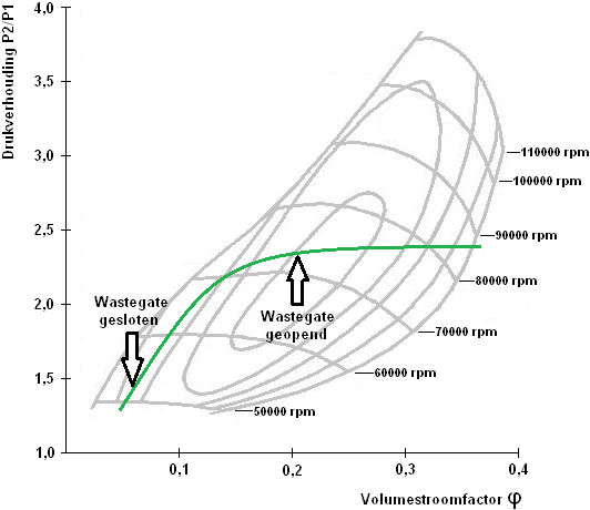
Thus, the size of the turbo is very important for the design of the engine. Each turbo has been given a compressor characteristic during design. The compressor characteristic can be used to determine whether it is suitable for a particular engine. The figure below shows an example of a compressor characteristic.
The pressure ratio P2/P1 (on the Y axis) is the ratio between the inlet (P1) and the exhaust of the turbo (P2). The pressure after the turbine wheel is always lower than before. The (dimensionless) pressure ratio of 2,0 means that the pressure before the turbine wheel is twice as high than after the turbine wheel. The volume flow factor (on the X-axis) is the amount of air that flows through the turbo. The curved, horizontal lines indicate the speed of the turbo shaft.
The picture shows that the red line is the surge line and the blue line is the choke line. The surgeline, also known as the pump limit, is the limit where the compressor wheel speed is too low. The surgeline is the restriction of airflow through the undersized compressor wheel. The pressure ratio is too high and the volumetric flow too low. The air is no longer drawn in by the compressor, so it stops and later resumes speed. This unstable airflow causes pressure fluctuations and pulsations in the inlet path. The pulsing is also called the “surging” of the compressor. Hence the name "surgeline". The air flowing back and forth causes great forces that can overload the turbo. The vanes of the compressor wheel can break off and overload the bearings.
The chokeline is another limit that the compressor must not exceed. Here the maximum volume flow prevails at a low pressure ratio. The diameter of the compressor housing determines the maximum volume flow. When the chokeline is exceeded, the compressor wheel is too small to handle the (larger) volumetric flow. As a result, a lot of engine power is lost. The chokeline is also called the "overspin choke".
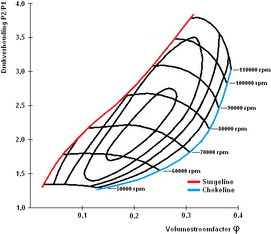
The figure shows the compressor characteristic of a motor in partial load. At partial load, the engine should have the lowest fuel consumption. The lowest specific fuel consumption is achieved with the smallest island. The wastegate regulates the pressure so that it runs right through the middle island. In the beginning, the wastegate is closed, so that the turbo pressure increases. The engine management system opens the wastegate as shown by the green line in the image. The speed of the turbo shaft is between 8000 and 9000 rpm.
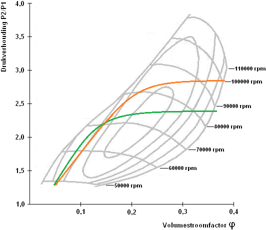
When driving in the mountains, there is a higher geographical elevation; the air is thinner there. This affects the functioning of the turbo, because thinner air contains less oxygen, which causes the pressure for the compressor to drop. The pressure ratio, so also the compressor speed, must increase in order to arrive at the final filling pressure. This situation can be seen in the picture.
The green line indicates the partial load situation when driving at sea level and the orange line when driving in the mountains. Due to the thinner air, the compressor speed will increase to 100000 revolutions per minute.
Due to the higher speed of the compressor, the temperature of the intake air supplied to the engine will also rise. The intercooler will therefore have to dissipate more heat. Now you can also see the difference in fuel consumption; in the mountains, fuel consumption will increase due to the higher pressure ratio P2/P1 and the higher turbo speed.
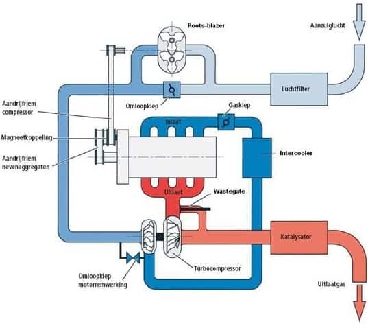
Combination of turbo and compressor:
Nowadays, car manufacturers increasingly choose to equip the engine with a turbo and a compressor. The turbo then often has a larger size and is equipped with a waste gate. The compressor serves to prevent the turbo lag; at low engine speeds, the compressor provides the boost pressure and starts the turbo. At higher revs, the turbo takes over.
The compressed air goes through the compressor or bypass valve to the turbo and through the turbo through the intercooler to the intake manifold.
Click here to learn more about the Roots compressor.
Electronic turbo:
A conventional turbo suffers from a turbo lag at low speeds, because exhaust gases are needed to drive the turbine wheel. A compressor does not suffer from this and already supplies charging pressure from idling speed. A combination of the two seems ideal. However, a Roots mechanical compressor must be driven by the crankshaft. Energy is lost in this. Car manufacturers are therefore experimenting with multiple exhaust gas turbos or electric turbos to prevent the turbo lag of the exhaust gas turbo.
The electric turbo is controlled by the engine control unit. In just 250 milliseconds, the compressor wheel reaches a speed of no less than 70.000 revolutions per minute. The electric motor in the turbo drives the compressor wheel. The compressor wheel moves the charge air under pressure to the compressor wheel of the exhaust gas turbo. The compressor wheel spins up very quickly when the electric motor is controlled.
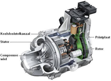
With the help of the electric turbo, the engine has a faster response. At higher speeds, where the exhaust gas turbo is able to supply the full boost pressure, the electronic turbo is switched off.