Introduction:
The pistons move up and down in the cylinder. The cylinder is fixed in the engine block and does not move. The piston constantly travels from BDC (Bottom Dead Center) to TDC (Top Dead Center) in the cylinder. At the top of the piston (known as the “crown”), combustion takes place. As the intake valves open and the piston moves down (BDC), a vacuum is created in the intake section. This vacuum draws air (or a fuel mixture) into the cylinder. In a force-fed engine (using a turbocharger or supercharger), the intake air is pushed into the cylinder at a certain overpressure.
The intake valves close and the piston moves up. The air (or fuel mixture) is then compressed and subsequently ignited in a gasoline engine with a spark plug and in a diesel engine by adding diesel fuel.
When the mixture ignites, the piston is forced down with great power. The exhaust valves then open, and the piston pushes the burned gases into the exhaust on the upstroke.
Pistons must meet the following criteria:
- As low a mass as possible to keep the forces at TDC and BDC as low as possible. Small mass forces put less stress on the bearings and allow higher rotational speeds.
- Good heat conductivity; the temperature of the piston crown can exceed 400 degrees Celsius. To prevent the temperature from getting too high, the crown is constantly cooled with an oil spray against the underside. The reduced thermal load results in less wear and lower oil consumption.
- Sufficient mechanical strength.
- Low friction coefficient.
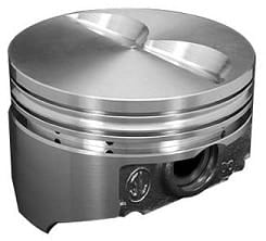
Piston Crown:
The top of the piston is called the “crown” or “piston crown.” Often, valve reliefs are machined into the piston crown.
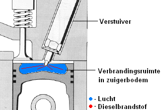
In direct-injection diesel engines, the piston crown is often also part of the combustion chamber. A special recess is machined into the piston to promote air swirling. The air in this space will swirl, allowing the diesel fuel to mix immediately with the air upon injection.
The image shows a direct-injection diesel engine with a pre-combustion chamber in the piston. In an indirect-injection diesel engine, there is a separate pre-combustion chamber in the cylinder head, so there is no combustion space in the piston crown.
Materials:
Pistons are usually made of aluminum or magnesium alloys. Sometimes forged aluminum pistons are used, with chromed piston crowns. These are very strong and lightweight. The advantage is that due to their light weight, they impose a lower mechanical load on the cylinder walls (resulting in less wear) and can be used in high-performance engines. Due to the specialized production, the price is significantly higher than that of regular aluminum pistons.
Small grooves are also applied to the side of the piston, comparable to the cross-hatch grooves in the cylinder wall. These are intended to “carry along” the oil during the piston’s up and down movement. Without these small grooves, the oil might simply bypass and enter the combustion chamber.
Piston Rings:
Piston rings must ensure the best possible gas seal between the piston and the cylinder. Leaks along the piston rings cause:
- Compression loss (leading to power loss).
- Oil loss through the combustion chamber.
- Premature ageing and contamination of the oil; gases leak into the oil, allowing them to mix, which ages the oil.
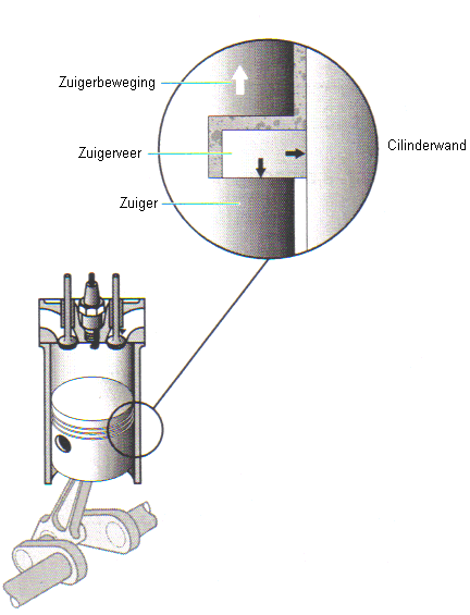
There is always a thin layer of oil between the piston ring grooves and the piston rings (see the image below). It is not possible for the piston rings alone to ensure sealing. The oil plays a crucial role here. It works as follows:
- When the piston moves up, the piston rings move to the lower part of the piston ring groove. (see image)
- Oil on the cylinder wall penetrates between the piston ring and piston ring groove, pressing the piston against the cylinder wall.
If the oil control rings are worn out, oil can penetrate between the cylinder wall and oil control ring, allowing it to enter the combustion chamber. The oil will then burn, resulting in blue or black smoke from the exhaust. Blue smoke is from engine oil that evaporates directly and unburned into the exhaust. With black smoke, the oil has participated in the combustion process and the burnt oil residues exit as (black) soot from the exhaust.
Piston Ring End Gap:
The end gap is the space between the two ends of the piston ring. If the end gap is too small, the piston ring has no room to form into a smaller diameter. This can result in damage to the cylinder wall and cause the piston ring to break. If the end gap is too large, there is too much space between the ends; the piston rings will not seal properly, leading to compression loss or increased oil consumption.
The end gap is measured with a feeler gauge. For the above measurement, the end gap should be between 0.35 and 0.55 mm. The feeler gauge with a thickness of 0.5 mm could be moved through with some resistance. So, the end gap is correct. For more information, see the page “piston ring measurements” under the header Mechanical Diagnostics.
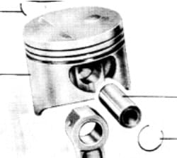
Piston Pin:
The piston pin connects the piston pivotally to the connecting rod. The piston pin is (theoretically) mounted in the center of the piston and is secured with a circlip. In reality, the piston pin is offset from the center, enhancing performance. More information on this is provided below in the next chapter: Piston Pin Offset.
Piston Pin Offset:
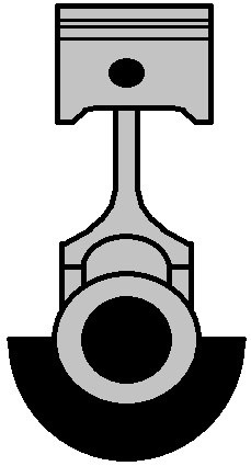
Piston pin offset means that the piston pin is not placed exactly in the center (as shown in the image). These pistons must, of course, also be mounted in a specific direction. The direction is indicated by an arrow marked on the piston crown. This arrow points towards the timing side.
The offset positioning of the piston pin serves an important purpose; it reduces the wear on the cylinder wall and the noise produced by the piston when shifting against the cylinder wall. When the piston moves upward, it presses against the left side of the cylinder wall and downwards to the right side. During each power stroke, the piston is thrust from the left side with significant force to the right side.
Because the piston pin is offset, the connecting rod is already upright before TDC. The piston moves to the right side of the cylinder before the power stroke. When the power stroke occurs, the piston is already in the correct position and can move in one straight motion downward. As the piston pin is offset, the piston is no longer slammed against the cylinder wall during the power stroke, which reduces noise and wear.
Piston Deformation:
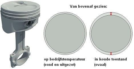
The piston takes on a different shape when the engine is warm compared to when it is cold. The material expands with heat. The piston is engineered so that expansion occurs in only one direction. Otherwise, the piston could seize in the cylinder.
On the far left in the image, the piston is shown in its normal condition. The middle section shows the piston in the cylinder viewed from above when it is at operating temperature. The engine has been running for some time, causing the piston’s material to warm and expand. The right section shows the piston in its cold state. It is now oval in shape. The arrows above and below indicate the size difference. The piston in the right image is reinforced in width and engineered in length to provide space for expansion. The reason being, any material expands when heated. The piston must have room to do so.
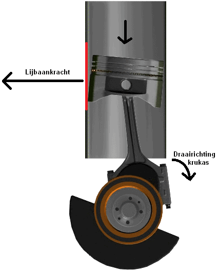
The side that does not expand, so in the image the left and right side of the piston, is pressed against the cylinder wall during the power stroke. This side absorbs the force of combustion (see the image below the “tilting piston” section). This is, of course, constructed this way because otherwise, the gap between the piston and cylinder wall is too large against this vast force. When the engine is cold, the piston would slam against the cylinder wall and have a shortened lifespan.
Despite this, the sound of the engine when cold can be different from when warm. In a cold engine, there is sufficiently more clearance between the piston and cylinder that a slight ticking sound might be audible. This is not an issue, provided the engine is warmed gently. By that, I mean that the engine should be warmed gently (not too high revs and definitely not too much throttle in low revs). If this is not adhered to, the piston is not fully expanded and the oil is not at min. 60 or 80 degrees operating temperature. The engine will then have a significantly shorter lifespan. The cylinder wall will wear down faster, as well as the side of the piston which will wear out easily. The noise of the piston can also be reduced by applying “offset” (see above section: Piston Pin Offset).
Tilting Piston:
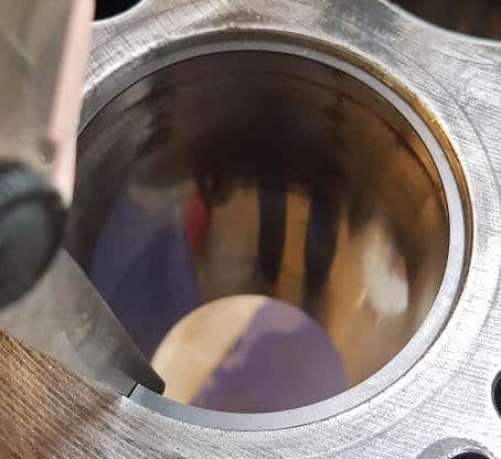
As the piston moves up and down, it also moves slightly sideways in the cylinder wall. If wear and tear occur in the cylinder wall due to improper engine use (consider high-speed driving/high revving with a cold engine), the (marked red in the image) part of the cylinder wall may wear down. Poor material choice by the car manufacturer can also play a big role (consider specific 1.4 16v engines from V.A.G.). This means the width of the cylinder wall increases and the piston gains more freedom of movement resulting from the force of combustion. In this case, it is referred to as “tilting pistons.” In the image, the piston is shown slightly tilted in the cylinder. A slightly exaggerated situation, but it makes the concept of “tilting piston” clear.
The result of tilting pistons is that the engine makes many ticking sounds. Sometimes it can almost be compared to the noise a diesel engine makes. The sound is purely from the piston slamming against the cylinder wall due to the extra space it has in the cylinder. This often increases oil consumption (due to poor sealing) and also leads to increased wear. The only remedy for this is to overhaul the engine.
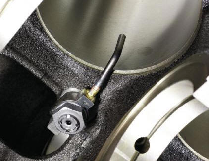
Cooling:
The piston is cooled by spraying engine oil against the underside. This can be done with an oil spray nozzle (see image below), or via a hole in the connecting rod. This is described, along with more information on cooling and lubrication, on the page lubrication system.