Subjects:
- Preface
- Switching on the HV system
- Interlock
- Short circuit protection
- Permanent insulation monitoring
- Diagnosis with the Megohmmeter
Preface:
The HV system in vehicles with an electrified or fully electric drive is equipped with multiple protections. The system cannot be armed until all safety requirements have been met. The moment an error is detected, the HV system switches off immediately. This can happen in the following situations:
- A part of the HV system is dismantled, and the system is switched on.
- Due to a collision or water damage, electrical parts or wiring short-circuit with each other or with ground.
- Parts have been damaged due to overload.
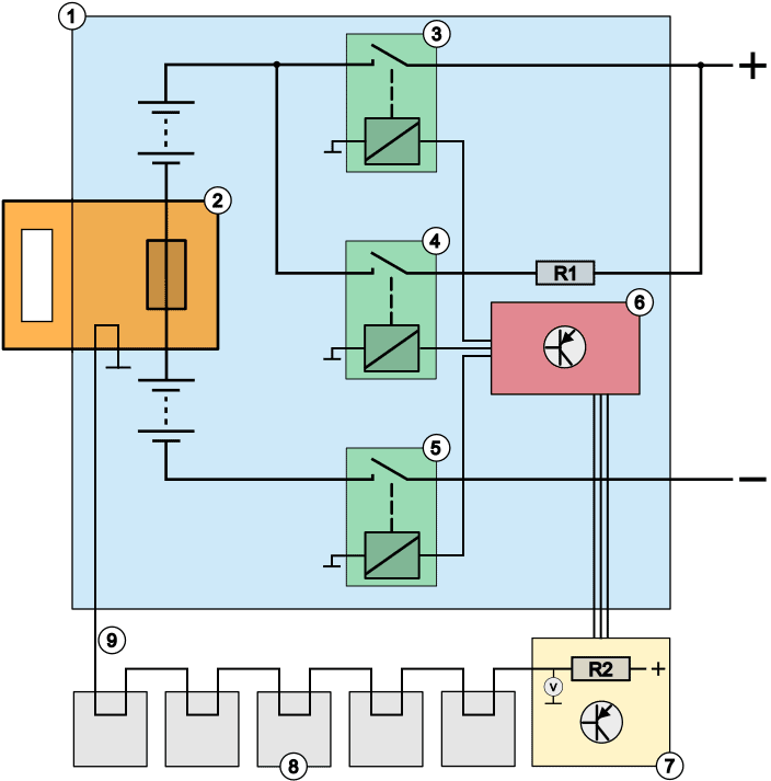
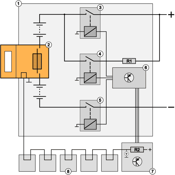
The image below shows the components that belong to the security system. Part of the HV battery (1) can be seen in blue, with the orange service plug (2) on the left. In the middle there are three relays (3 to 5), which are switched on one by one by the ECU (6). Below the HV battery is the ECU (7), which is connected to the consumers (8), such as the electric motor, heating, air conditioning pump, power steering and charging system.
Description:
1. HV battery
2. Service plug with fuse
3. Relay 1
4. Relay 2
5. Relay 3
6. ECU of HV battery
7. ECU of HV system
8. Electrical consumers
Switching on the HV system:
The driver activates the HV system by pressing the start button. The moment the message “HV ready” appears in the display, the HV system is activated. Before the HV system is active, the relays in the HV battery pack controlled to connect the battery pack to the consumers.
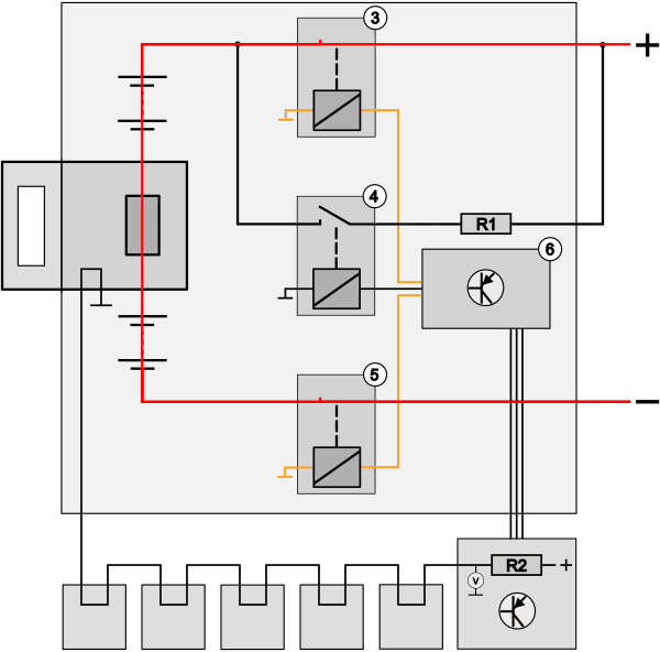
When the HV system is turned on, the ECU (6 in the figure below) controls the HV relays in the positive circuit (relay 4) and the ground circuit (relay 5). First, the current circuit on the plus side is switched on via a resistor. In the image below we see that relay (4) passes the current to resistor R1. The resistor limits the current passing through it, thus limiting the inrush current. This allows the capacitors in the inverter to be charged slowly. At this time the system can perform a safety check at a lower voltage. After the voltage across the capacitors in the inverter is approximately equal to the voltage of the HV battery pack, relay 3 closes and relay 4 opens, applying full voltage to the inverter and other electrical components.
Interlock:
The interlock system is the security system that provides protection against electrical contact when there are open connections. In each component connected to the HV battery there is at least one contact that can shut down the HV system when an interruption occurs. These contacts can be integrated into the wiring or incorporated into the housing of a component as a switch.
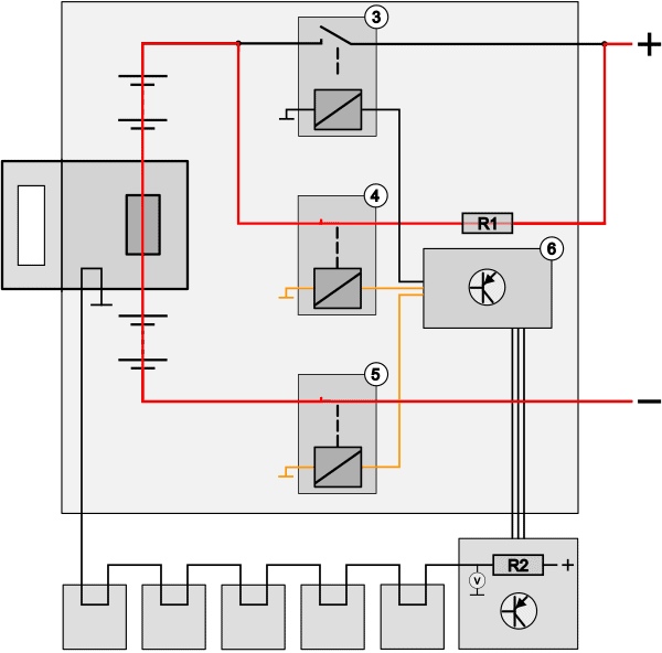
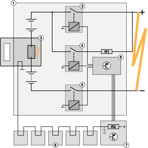
In the image below left we see the active system: relays 3 and 5 are closed, which means that the voltage from the HV battery is transferred to the consumers. The interlock circuit is colored blue from the vehicle ECU (7). A voltage is applied to resistor R2 from the ECU. The interlock is routed through the electrical consumers (8) as a series circuit. The interlock is connected to ground in the battery pack. There is a branch between resistor R2 in the ECU (7) and the output to the consumers where the voltage on the interlock is measured.
- Interlock OK: voltage after resistor R2 is 0 volts;
- Interlock interrupted: the voltage is not consumed in the resistor R2 and is (depending on the supply voltage) 5, 12 or 24 volts.
The voltage after resistor R2 is constantly monitored during switching on, but also while driving.
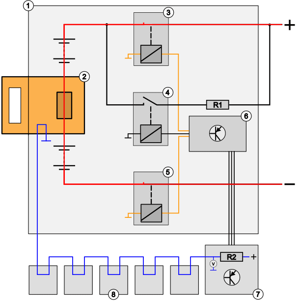
Dismantling the service plug (2) or any of the electrical components (8) also breaks the interlock circuit. This situation can be seen in the right image above, where the service plug has shifted. Both the fuse between the battery modules and the interlock circuit are open. Because the interlock is no longer connected to the vehicle ground, the voltage after resistor R2 rises to the value of the supply voltage. The vehicle ECU (7) directly controls the battery ECU (6), so that relays 3, 4 and 5 are no longer activated. The HV system is then switched off.
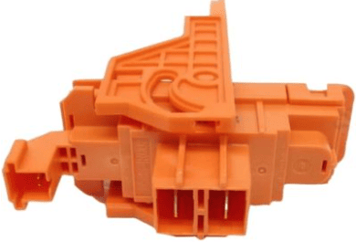
In the image we see the orange service plug with the large contacts in the middle to connect the positive and negative cables of the HV battery, and on the left a smaller plug connection with two pins. These are the two pins of the interlock. We also find these connections on plugs of HV components.
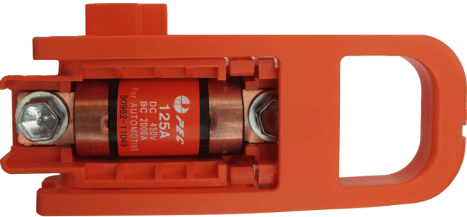
Short circuit protection:
The HV system must be protected against excessive currents, which can be caused by a short circuit in the wiring or in the electrical components. Without protection, this can lead to an arc flash, melting of pipes, or even fire. A fuse is designed to protect the system against these hazards. The fuse may be located in the service plug, but also elsewhere in the battery pack. Vehicles may also be equipped with multiple fuses, each designed to protect a specific circuit.
In addition to the fact that the fuse protects the system against excessive currents, the current sensor in the positive or negative cable of the HV battery transmits the current to the ECU. The ECU makes the decision to switch off the relays when there is an overload.
Permanent insulation monitoring:
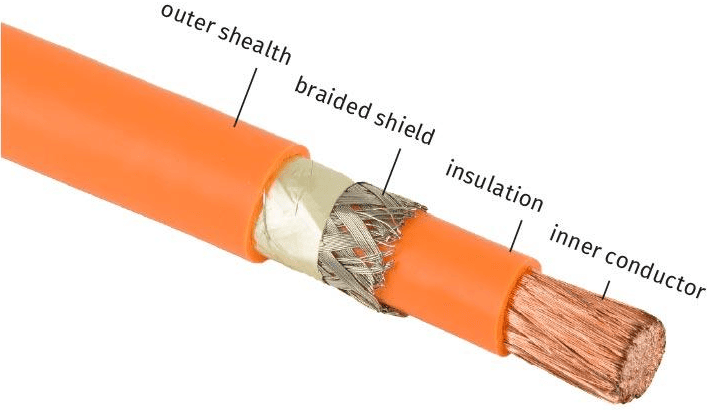
The positive and negative sides of the HV battery do not come into contact with each other, nor with the environment. There are several layers of insulation around the plus side (from the + battery to the + of the inverter) with a braided sheath in between. But the minus side is also insulated and does not make contact with the bodywork or housing of the components. The body of the vehicle itself, on the other hand, is connected to the negative of the on-board battery (12 volts in passenger cars). This is not the case in the HV part. Causes of a malfunction can be:
- After a collision, damage may have occurred to the wiring, causing the copper of the positive and negative wires to come into contact with each other or to touch the body of the vehicle;
- due to overload - and therefore overheating - the insulation in an electrical component has failed (melted), allowing contact with the environment;
- Or there is conductive liquid because the vehicle has been in the water, a short circuit has occurred between the plus and minus due to coolant leakage in the HV battery pack. Leakage of refrigerant in the electric air conditioning pump can also cause conduction.
In the electrical components, poor insulation can cause a connection between the positive or negative cables from the HV battery and the housing. Since the housing is usually mounted on the body of the vehicle, a current could arise if the protection is poor in the event of poor insulation. When the plus of the HV battery is connected to the vehicle body via the housing as a result of an insulation failure, high voltage of hundreds of volts is present on the bodywork. However, because there is no way to connect to the negative of the HV battery, nothing will happen because no current will flow. Things will only go wrong if there are multiple insulation failures, where both the plus and minus of the HV battery come into contact with the bodywork.
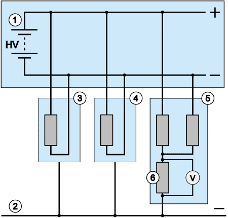
In the three images below we see the HV battery pack (1) with the positive and negative cables, with the vehicle body at the bottom (2) and two electrical consumers (3 and 4) in between.
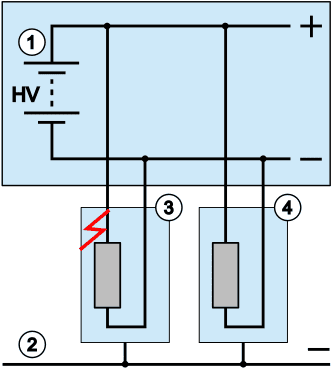
- poor insulation of the plus side of the component: if there is poor insulation between the plus and the housing in a consumer (for example an electric heater), the housing will become live. Because there is no connection to the negative of the HV battery, no current flows;
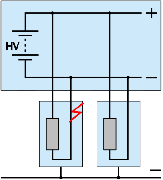
- poor insulation minus: again there will be a (small) voltage on the bodywork, but no current will flow;
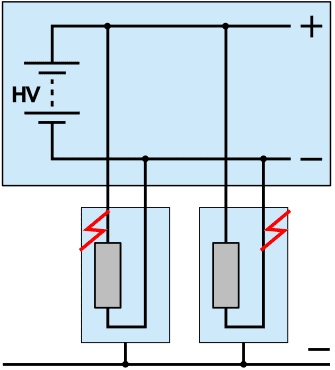
- poor insulation in both the plus and minus: in this situation there is a short circuit between the plus and minus of the HV battery. The bodywork becomes the connection between positive and negative. The current will increase rapidly until the fuse in the service plug and/or the HV battery blows to protect the system.
Because with poor insulation in the plus or minus there is not yet a closed circuit, the fuse in the service plug will not melt. The permanent insulation monitoring in electric vehicles detects such current transfer, warning the driver with an error message. With an insulation fault, the vehicle can still function, unless the manufacturer has it disabled via software.
Number 5 in the figure below indicates the component where permanent insulation monitoring takes place. In reality, this electrical part is of course more complex.
Number 6 indicates the measuring resistor over which the voltage drop is measured in parallel.
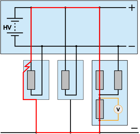
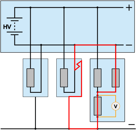
The two images below show the situations where there is poor insulation in the plus (left) and in the minus (right). Because current flows through the measuring resistor, voltage is consumed in the resistance circuit. The voltage drop across the measuring resistor is a measure of the amount of current flowing through the resistors.
As soon as the ECU detects an abnormality with permanent insulation monitoring, it stores an error code. Possible descriptions of the P codes (such as P1AF0 and P1AF4) could be: “battery voltage system isolation lost” or “battery voltage isolation circuit malfunction”. When a vehicle enters the workshop with an insulation fault, the mechanic can measure the insulation resistances after using the diagnostic equipment, or manually with a Megohmmeter, to check whether there is an insulation leak somewhere.
Diagnosis with the Megohmmeter:
The previous section explained the concept of "insulation resistance" and showed how the vehicle uses the permanent insulation monitoring to check whether there is a leak from the positive or negative connections from the HV battery to the body of the vehicle. In this section we will discuss this in more detail and describe how you, as a technician, can detect the location of the fault with a Megohmmeter. Naturally, as a technician you must be certified to work on HV systems. The software in a diagnostic tester can itself perform an insulation test for certain brands, for example for components that only show an insulation fault after being switched on, such as electric heating or electric air conditioning.
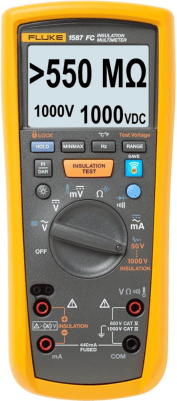
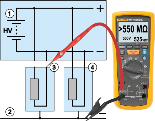
In other cases we can measure the insulation resistance with a Megohmmeter. It is not possible to measure insulation resistance with a normal multimeter, because the internal resistance of the multimeter can be up to 10 million ohms. The internal resistance is too high to measure high resistance values. A Megohmmeter is suitable for this and outputs a voltage of 50 to 1000 volts to simulate the operating situation. This high voltage ensures that the emitted current finds its way through the copper core to the insulation, even through the smallest damage in the insulation. To measure with the Megohmmeter, set the meter to the same voltage as that of the HV battery, or one step higher. After connecting the measuring cables and setting the meter correctly, we click on the orange “insulation test” button. The set voltage (in the image: 1000 volts) is applied to the measuring cables and therefore to the component, and we then read the ohmic value from the display.
- An insulation resistance greater than 550 MΩ (Megaohm, which means 550 million ohms) is OK. This is the maximum measuring range;
- A value lower than 550 MΩ may indicate a leak in the insulation, but this does not necessarily have to be the case;
- According to the International Electrotechnical Commission (IEC) and the Institute of Electrical and Electronics Engineers (IEEE), the insulation resistance of an EV must be at least 500 Ω per volt. At a nominal HV voltage of 400 volts, the resistance should be (500 Ω * 400 v) = 200.000 Ω.
- Manufacturers often set higher quality and safety standards, resulting in higher minimum insulation resistances. For this reason, the factory instructions must always be adhered to when making a diagnosis.
A manufacturer's instructions are always leading.
The factory specifications describe the steps, safety regulations and minimum insulation resistances.
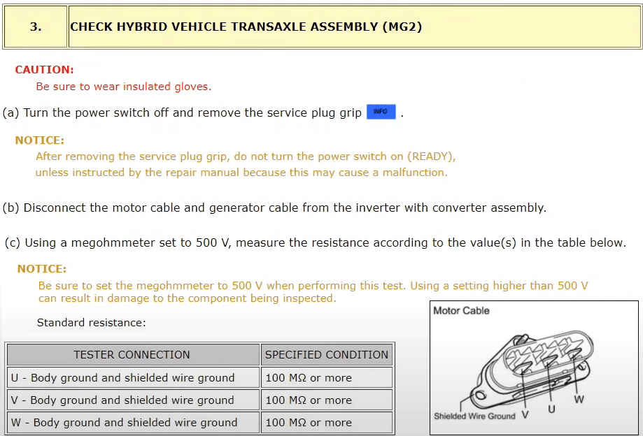
In the next image we see a screenshot from a Toyota manual. The minimum insulation resistances of the cables to the electric motor of the relevant model are shown.
The megohmmeter should be set to 500 volts and the minimum resistance of the wiring (UV and W) to the electric motor compared to the housing should be 100 MΩ (MegaOhm) or more.
The insulation resistances of, for example, the electric air conditioning compressor and heating element may be different. When measuring other components, refer to that part of the factory data.
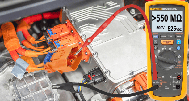
1. Insulation measurement on the negative side (no fault):
With the plug disconnected we also measure the negative side compared to the vehicle mass. Figures 1 and 2 show what this measurement looks like in schematic form and in reality. The measurement results in an insulation resistance of >550 MΩ, which indicates that the insulation is in good condition.
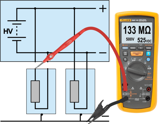
2. Insulation measurement on the plus side (no fault):
After disconnecting the plug, for example from the inverter, we attach the red measuring probe to the pin in the dismantled plug (now in the plus side) and the black measuring probe to a ground point connected to the vehicle body. Figure 1 re-displays the diagram from the previous section, numbering the HV battery (1), vehicle mass (2), and two of the consumers (3 and 4). The Megohmmeter is connected and the orange “insulation test” button has been pressed to measure the insulation resistance with the transmitted voltage of 500 volts. This amounts to 133 Megaohm. The insulation resistance is lower than in the previous measurement. Manufacturer's instructions should be consulted. We adhere to the minimum insulation resistance of 100 MΩ specified by the manufacturer. The insulation resistance is OK.

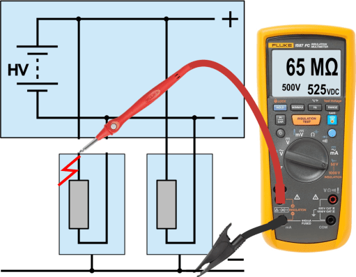
3. Insulation measurement on the plus side (fault):
While measuring on the same connections we measured an insulation resistance of 65 MΩ. Although the resistance value is higher than the minimum 500 ohms per volt set by the IEC and the IEEE (see the previous paragraph), the wiring and/or component is rejected because the manufacturer has specified the minimum resistance value of 100 MΩ. The wiring and/or plug connections may not be repaired, but must be completely replaced.
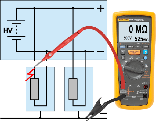
4. Insulation measurement on the plus side (fault):
When an insulation value of 0 MΩ is measured, there is a direct connection (i.e. short circuit) between the HV wire and the housing. The wiring and/or plug connections may not be repaired, but must be completely replaced.

In the event of an insulation fault, the plugs of other consumers can be disconnected one by one to measure in the plug, as shown in the text and images above.
Related page: