Subjects:
- Circuit of a PWM-controlled valve
Circuit of a PWM controlled valve:
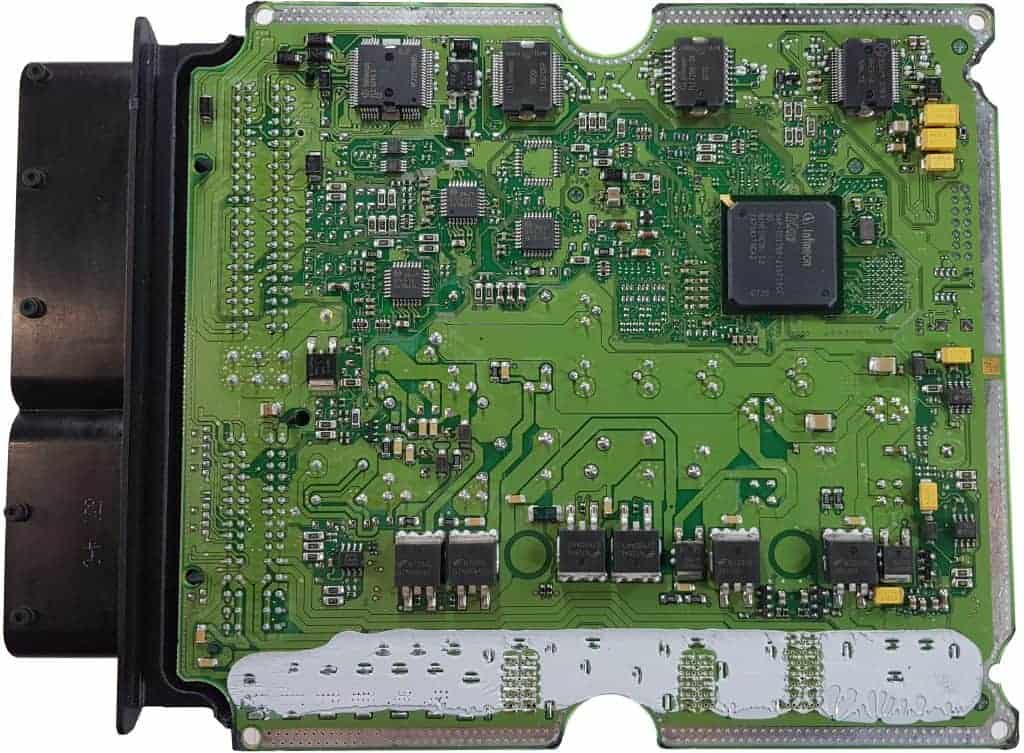
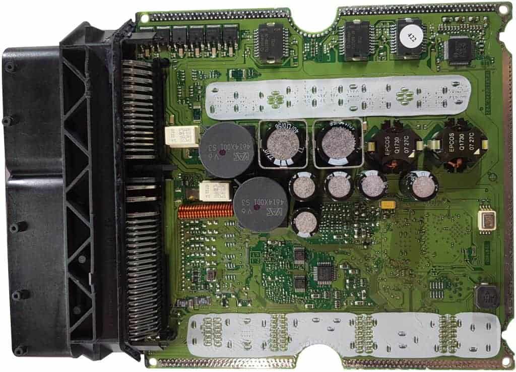
The two images below show the inside of a engine control unit. The covers have been removed. In this section we show an example of the circuit of a PWM controlled valve with a schematic and the connections. First, take a look at the top and bottom of the circuit board.
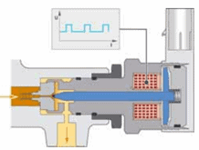
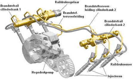
The PWM controlled pressure regulator is located on the high pressure line of the common rail. The figure below shows the solenoid valve being opened with a PWM signal. In addition, an overview of the common rail system can be seen.
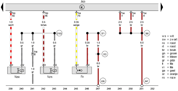
The schematic below is of a 3.0 common rail diesel engine (VAG). We are looking up the component code of the fuel pressure regulator: the N276.
The purpose of this fuel metering valve is to regulate the fuel pressure in the rail. With this engine, the pressure varies between 300 and 1600 bar, depending on the operating conditions.
The N276 receives a supply voltage on pin 2 (grey) that is equal to the on-board voltage (between 13 and 14,6 volts with the engine running). Pin 1 is connected with a brown/white wire to pin 45 in connector T60 on the ECU.
When the ECU switches the valve to ground, a current flows through the coil. In that case, the valve is energized and opens. If the ECU interrupts the ground, a spring in the fuel metering valve causes it to close again. By doing this very quickly in succession and by varying the period of time that the valve opens and closes, we can speak of a PWM control.
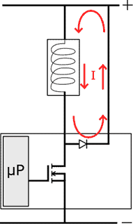
We are going to look at the circuit of this PWM control with the help of the diagram below and measurements in the plug and on the PCB of the ECU. How are the components actually connected? How are these visible on the printed circuit board? And what are the components for? That will become clear in this section.
The image below shows both the inside of the plug and the underside of the printed circuit board. By means of measurements with the multimeter, a search was made for the solder connection on the printed circuit board to which plug connection T60/45 is connected. These soldering points are indicated by the purple arrows.
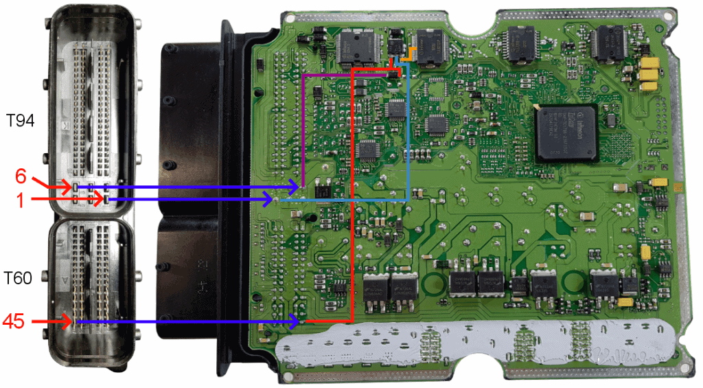
The negative connection of the fuel metering valve (1) is connected via plug connection T60/45 to the drain of the FET and the anode of the freewheeling diode. The red lines in the pictures indicate the solder joints. For clarity, an enlarged version of the above image is shown.
The source is connected to ground via plug connection T94/1 and is indicated by the blue line.
The microprocessor switches the FET on and off by applying a control voltage to the gate of the FET. The orange line shows the connection between the microprocessor and the gate of the FET.
The moment the gate receives a control voltage from the microprocessor, the FET becomes conductive and a current can flow from the drain to source and thus also through the coil. The magnetic field energizes the coil and closes the fuel pressure control valve.
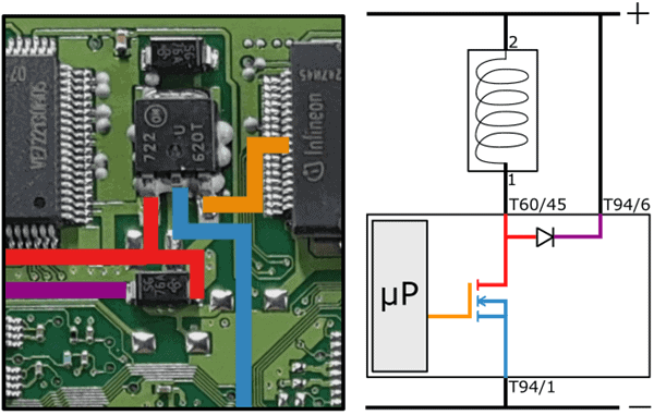
As soon as the control voltage on the gate is lost, the connection between the drain and source is broken. The freewheeling diode ensures that the induction current is fed to the plus as a result of the residual energy in the coil. This ensures a gradual current reduction and prevents an induction from occurring.
The fault diagram shows the contact resistance in the positive wire of the coil. The red arrows indicate the current direction when the FET is turned off. The current can decrease slowly thanks to this circuit.
Now that we've gone through the fuel pressure regulator circuitry and components, we can also look at the scope images if we're dealing with a malfunction. How do we recognize a malfunction in a PWM signal? What are the consequences for the operation of the pressure regulator? You can read this on the page duty cycle and PWM control.