Subject:
Decomposition of piston forces:
Above the piston, a pressure (p) arises due to combustion during the power stroke. The force generated is transferred by the connecting rod to the crankpin. The resulting moment (force * arm) causes the crankshaft to rotate. Here the torque of the engine is generated.
The following five images illustrate the forces occurring in the crank-connecting rod mechanism when the combustion pressure pushes the piston downward. An explanation of the force play is described for each enlarged image.
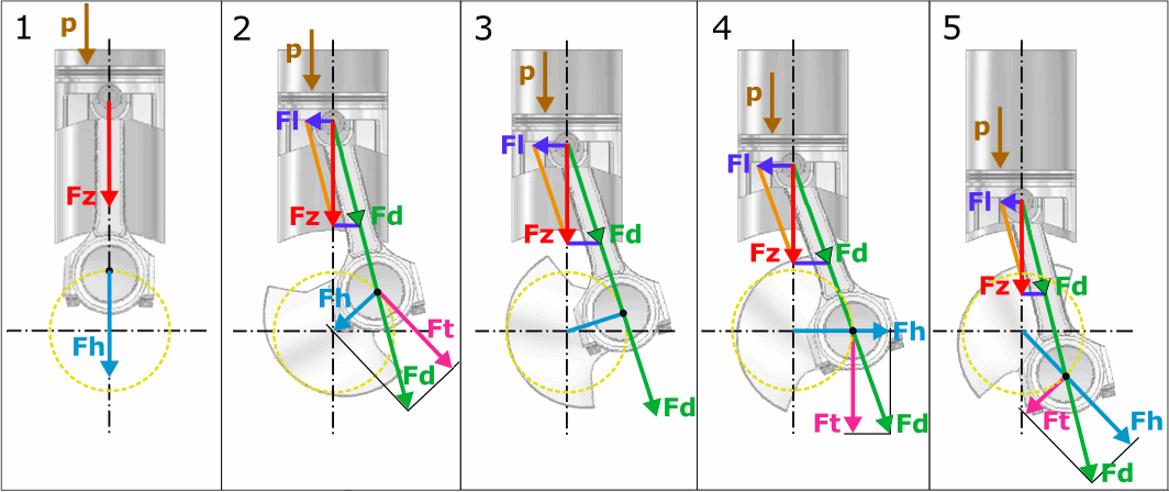
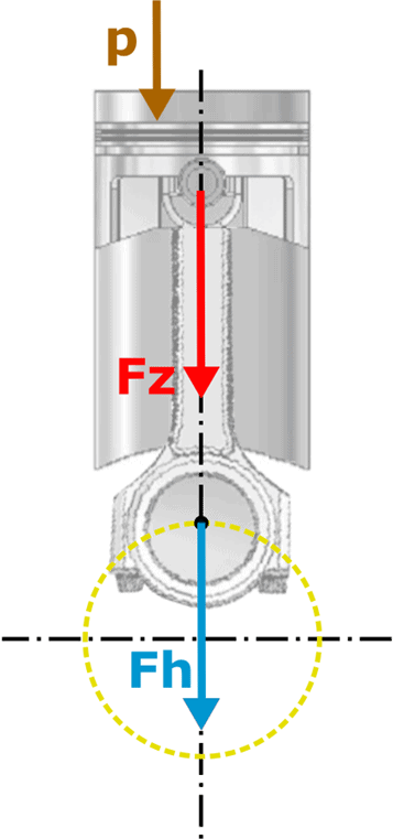
1. The combustion pressure (p) generates a force on the piston (Fz) and the main bearing (Fh). We can determine this force using the indicator diagram.
The force Fz is passed to the connecting rod. In this situation, the connecting rod stands perpendicularly above the crankpin and the main bearing (Fh). The actual combustion, where the pressure p is maximal, occurs approximately 8 crankshaft degrees after the TDC. The force Fz is as high as the force with which the connecting rod and main bearings of the crankshaft are loaded. We can therefore write: Fz = Fh.
In this image, a yellow dashed line runs from the center of the crankshaft to the center of the crankpin. The midpoint of the connecting rod (black dot) circles around it.
In this situation, there is no decomposition of the piston forces yet. The force on the main bearing is at its highest in this position.
Summary of the abbreviations used:
- p: combustion pressure;
- Fz: piston force;
- Fh: force on the main bearing
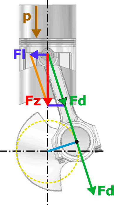
2. The force from the piston is transferred via the connecting rod to the crankpin. We decompose the force on the piston (Fz) and on the connecting rod force (Fd) that runs in the direction of the connecting rod.
As a result of the tilting of the connecting rod and force Fz, the piston is pressed against the cylinder wall. This force is indicated by Fl (guiding force). At this point, the piston and cylinder wear the most.�a0
The connecting rod force Fd acts on the crankpin and decomposes due to the rotation on the crankpin into the tangential circumferential force (Ft) and the radial force on the main bearing (Fh). The radial force transfers the force via the upper connecting rod bearing to the crankshaft.
The tangential force (Ft) depends on both the connecting rod force and the position in which the crank-connecting rod mechanism is located. Because the tangential force is decisive for the engine’s torque, the torque constantly changes in magnitude. The mass of the flywheel ensures that these changes in torque do not directly affect the crankshaft rotational speed.
Summary of the abbreviations used:
- p: combustion pressure;
- Fz: piston force;
- Fd: connecting rod force;
- Fl: guiding force;
- Fh: force on the main bearing;
- Ft: tangential force.
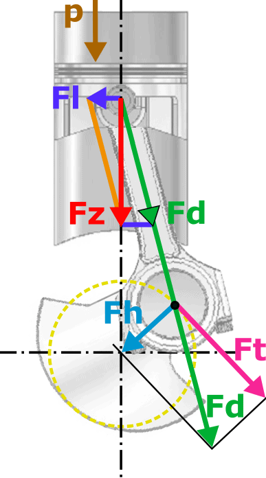
3. The centerlines of the connecting rod and crankpin are at a 90-degree angle to each other. The tangential force (Ft) is now as great as the connecting rod force (Fd) and, like the obtained torque /�a0torque, is at its highest at this point. We can therefore write: Fd = Ft.
The main bearing is not loaded now. There is no force Fh. We can note: Fh = 0
Summary of the abbreviations used:
- p: combustion pressure;
- Fz: piston force;
- Fd: connecting rod force;
- Fl: guiding force;
- Fh: force on the main bearing.
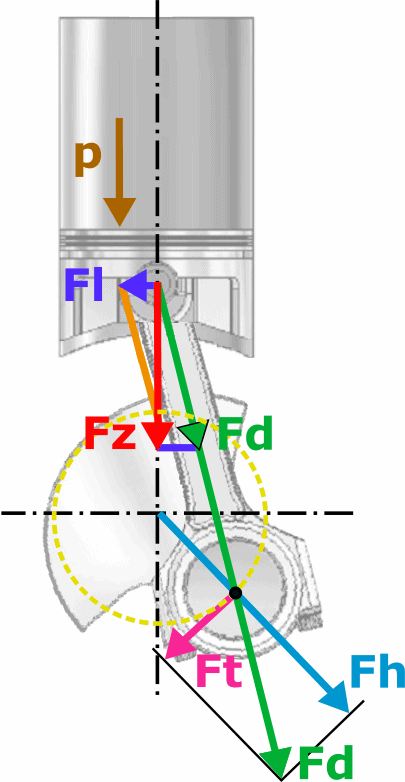
4. As the crankshaft continues to rotate, the tangential force (Ft) decreases. The tangential force is no longer in line with the connecting rod force.
The guiding force (Fl) has now increased because the angle in which the connecting rod is positioned is maximal.
Summary of the abbreviations used:
- p: combustion pressure;
- Fz: piston force;
- Fd: connecting rod force;
- Fl: guiding force;
- Fh: force on the main bearing;
- Ft: tangential force.

5. The piston moves further towards the BDC. The force on the main bearing (Fh) increases and is maximal when the piston reaches the BDC completely.
The guiding force (Fl) has also decreased; this force becomes 0 N when the piston reaches the BDC.
Summary of the abbreviations used:
- p: combustion pressure;
- Fz: piston force;
- Fd: connecting rod force;
- Fl: guiding force;
- Fh: force on the main bearing;
- Ft: tangential force.