Introduction:
The air conditioning system is responsible for cooling and dehumidifying incoming air, which helps create a comfortable environment for the vehicle occupants. In addition to improving comfort, a pleasant climate also affects the driver’s alertness. Air conditioning is part of the so-called HVAC, which stands for: Heating Ventilation Air Conditioning. A vehicle with HVAC can therefore heat, ventilate, and cool the climate system. In the literature, we are seeing the term HVAC more and more often.
The extent to which an air conditioning system can lower the temperature can vary depending on several factors, such as ambient temperature, system efficiency, and the desired temperature setting. In general, it is common for a properly functioning air conditioning system to cool the temperature in a passenger car by about 10 to 20 degrees Celsius compared with the outside temperature. To quickly bring the outlet air temperature to the desired level, it is recommended to activate the recirculation mode. This function ensures that the already cooled air in the cabin is routed through the evaporator again for additional cooling.
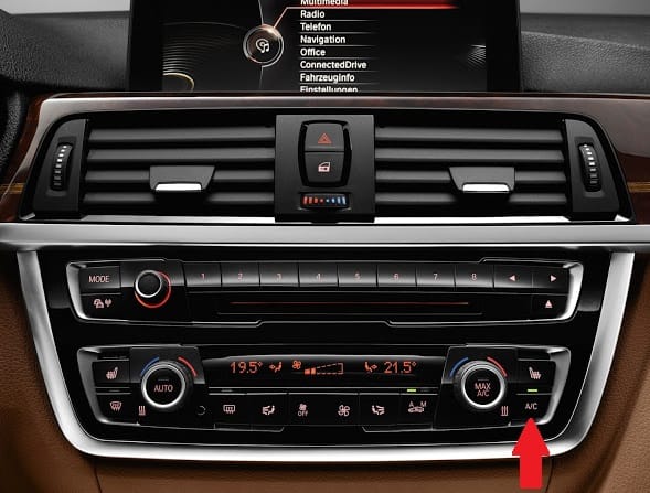
The following image shows the control panel of a BMW 3 Series. The air conditioning (A/C) button is indicated with a red arrow. The A/C is switched on.
This page provides a brief overview of how the air conditioning system works. In each paragraph, you can click the topic to go to the page where more detailed information is provided about that topic.
Operation of the air conditioning system:
In an activated air conditioning system, refrigerant circulates through the various components of the system. This refrigerant undergoes two state changes:
- condensing: heat is released to the surroundings. During condensing, the refrigerant changes from a gaseous state to a liquid;
- evaporating: heat is absorbed from the surroundings. Evaporation takes place in the evaporator, which cools the air flowing to the cabin.
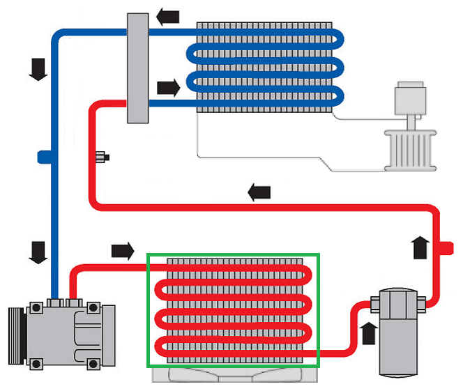
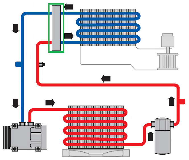
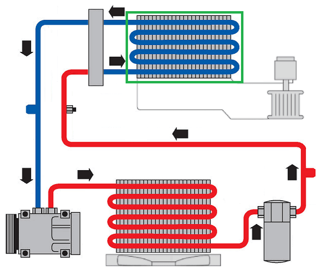
The image below shows an overview of the components of a modern air conditioning system. The refrigerant circuit can be divided into two pressure zones: high and low pressure. In the image below, the red line is the high-pressure side and the blue line is the low-pressure side.
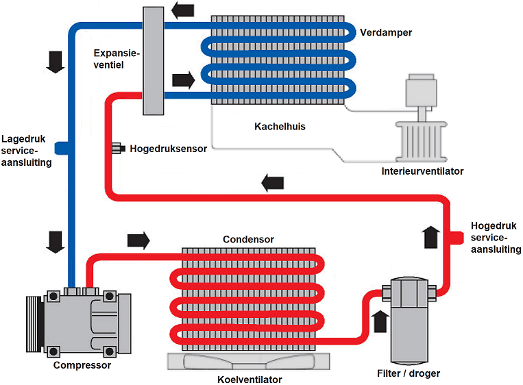
In the next paragraphs, the diagram above is shown again, with each component individually highlighted with a green frame. For each component, detailed explanation is provided about its operation, its location in the vehicle, and its interaction with other components. First, the components that are directly responsible for the refrigeration cycle are described. Each component has a subpage that goes into more detail about its operation. Click the blue-colored text to do so.
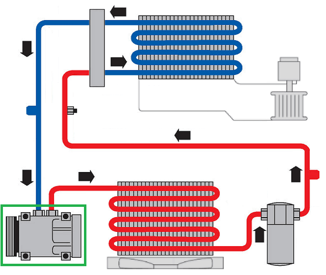
Compressor:
The A/C compressor draws in the gaseous / vapor refrigerant through the blue line and increases its pressure. Increasing the pressure also raises the boiling point. The vapor is then routed through the red line to the condenser. The vapor remains superheated. The A/C compressor has a pulley that is driven by the serpentine belt. The compressor can be switched on and off using an electromagnetic clutch. In electric or hybrid vehicles, the drive can be provided by an electric motor in the HV system instead of the serpentine belt.
The A/C compressor in cars with internal combustion engines is located in the engine compartment on the serpentine-belt side, and is driven by the serpentine belt together with the alternator and, if applicable, the power steering pump. In the case of electric vehicles, the compressor may be located in the cabin and an electric motor drives the (electric) A/C compressor.
Condenser:
After the refrigerant has left the compressor, pressure and temperature have increased significantly. The condenser is tasked with condensing the superheated vapor from the compressor into a subcooled liquid. When the temperature drops below the boiling point, the refrigerant becomes liquid. In the condenser, heat is discharged to the outside air. While driving, ram air flows through the condenser. If flow and cooling are insufficient, the fan switches on to increase airflow. The outside air flowing through the condenser is then warmed up.
The condenser is located at the front of the car, in front of the cooling system radiator.
Expansion valve:
The liquid refrigerant arrives at the expansion valve under high pressure. The expansion valve causes a sudden pressure drop, which lowers the pressure, temperature, and boiling point. The liquid changes into saturated vapor. This is a mixture of vapor and liquid particles. In the expansion valve, the high and low pressure sides are separated from each other.
The expansion valve is available in different versions: with a fixed restriction (capillary tube) or a variable restriction (thermostatic expansion valve).
Evaporator:
The task of the evaporator is to cool the incoming air to the car’s cabin. The cabin blower blows outside air or recirculated cabin air through the evaporator fins. Heat is absorbed from the passing air. The cooled air is then blown into the cabin.
From the expansion valve, the vapor refrigerant flows to the evaporator. Temperature, pressure, and boiling point are low when it flows in. The airflow through the evaporator warms the refrigerant, causing it to start boiling immediately. When leaving the evaporator, the refrigerant is in a superheated state. After the refrigerant has evaporated at the moment it leaves the evaporator, the cycle starts again. The compressor draws in the gaseous refrigerant again to compress it again.
The evaporator is installed in the heater/ventilation housing behind the dashboard.
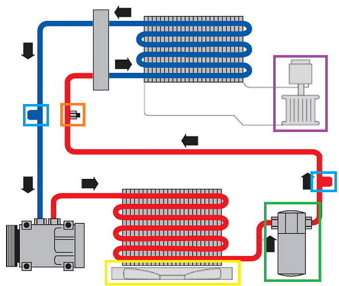
The last image shows the components that were not mentioned above.
- Service ports: these are outlined in blue. They are used to check pressures with a manifold gauge set, and to evacuate or recharge the system;
- High-pressure sensor: the sensor outlined in orange measures the pressure in the high-pressure line. Among other things, the engine ECU can use this to control the compressor output;
- Cabin blower: the cabin blower outlined in purple blows air into the heater box and therefore also through the evaporator;
- Cooling fan: the cooling fan outlined in yellow blows outside air through the condenser. Some cars have a separate fan for the condenser, and other cars use the cooling fan that also cools the radiator;
- Filter / drier: filtering dirt particles and drying (dehumidifying) takes place in the element outlined in green. The filter / drier element can be mounted directly next to the condenser, but it can also be located inside the condenser.
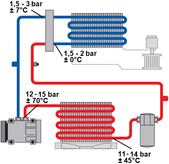
Pressures and temperatures:
By measuring pressures and temperatures at different points in the system, we can determine whether the system is functioning correctly. Because the pressure and temperature of the refrigerant depend on the outside air temperature, we use as a guideline a temperature between 25 and 30 °C and an increased engine speed so that the A/C compressor has sufficient capacity.
Due to compression, the refrigerant temperature when leaving the compressor rises to about 70 °C, while pressure varies between 12 and 15 bar. The refrigerant reaches the expansion valve via the drier/filter, where a pressure drop occurs and the temperature drops to just above freezing. When the refrigerant leaves the evaporator, it has warmed up a few degrees due to the air that has passed through.
On the page: Diagnosing air conditioning using pressure and temperature the most common faults, causes, and solutions are described.