Topics:
- Preface
- VAG Diagrams General
- VAG Diagrams: Wire Colors, Thickness, Component Codes, and References
- VAG Diagrams: Connector Codings and Pin Assignments
- VAG Diagrams: Positive, Ground, and Signal Wires of an Active Sensor
- VAG Diagrams: Shielded Wires
- VAG Diagrams: Networks
- Assignment: Reading VAG Diagrams
- HGS Data Lighting Diagram
- HGS Data Wiper Diagram
Preface:
The diagrams on this page are at all times intended for educational use. The emphasis is not on the type of car or version, but on the explanation of how such a diagram should be read. The relevant vehicle data and data irrelevant to the explanation are omitted.
The following sources of information were used for the diagrams:
- VAG Diagrams: ElsaWin / ErWin;
- HGS Data Diagrams: Hella Gutmann Solutions.
Inquire with the aforementioned manufacturers / developers to gain access to their database. Sometimes there is a yearly subscription, other times one can purchase login time of e.g. one hour, 24 hours, a week, month, or year.
The owner of this website does not provide diagrams to third parties and does not claim copyright over the diagrams shown below.
VAG Diagrams General
The following paragraphs include some diagrams from VAG (VW, Audi, Seat, Skoda). Explanations are given about the meanings of some symbols, abbreviations, and references.
Each diagram features component codes. These codes are meant to keep the diagram organized and not overloaded with text. This way, it is also easier to keep diagrams universal. Translating a legend is easier than implementing language changes in each individual diagram. Only the most important components necessary for the explanation are mentioned in the text.
VAG Diagrams: Wire Colors, Thickness, Component Codes, and References:
We look at the meanings of the abbreviations of wire colors, thickness, components, and references in the VAG diagram.
In the lower left corner of the diagram, the battery is shown with the component code A. If we follow the striped line upwards, we arrive at a connection to SA. 0
The striped line is actually a direct connection to the fuse box. SA is the component code for the fuse box on the battery.
In the gray block under SA are SA1 through SA7. These are the fuses; SA1 is the first fuse in this component.
The shape of the fuse box in the diagram shows that it is actually larger; the serrated lines on the left and right indicate that the fuse box will continue in a subsequent diagram with more fuses.
A black line runs downwards from SA1; it leads to component C. In the legend, we find that C is the code for the alternator. The black wire on the alternator is connected to B+. The B+ is the (battery-positive) connection fused to the positive terminal of the battery.
The wire thickness is 16.0 mm², and the color sw stands for “schwartz” in German, which means black in Dutch.
On the alternator, we find two more connections, one ground connection (direct to the engine block) and one LIN-bus connection. This involves a blue 0.5 mm² wire that transitions to a violet-white (vi/ws) 0.35 mm² wire. The LIN-bus wire is also connected to J367 (control unit for battery monitoring) and goes to reference 200. We will return to this reference later.
Control unit J367 is connected to fuses SB22 and SC5 with two wires. At the top, asterisks (*) are visible.
At SB22 *, and at SC5 *2. This is related to the model year: * up to May 2010 and *2 from May 2010. If we are dealing with a car from 2011, the red/yellow wire to fuse 5 in fuse box SC applies.
A black 25 mm² wire runs from control unit J367 to a grounding point with code 624. The dot is colored white: this is a screw connection to the car body.
With code 624, we can find the exact location in the vehicle. The black dots on the same horizontal line are junctions: these ground wires are connected to screw connection 624. This is a shared grounding point on a screw connection and is also known as a “grounding splice.”
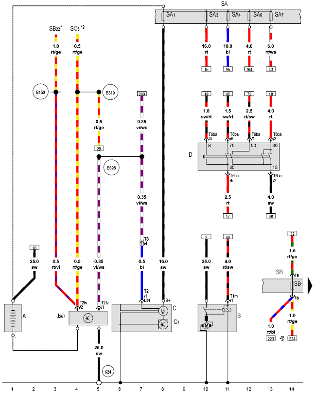
In the above diagram, we also see components B (the starter motor) and D (the ignition switch). This section is highlighted in the next diagram. Above the starter motor (B), we see two wires: a thick black wire (25 mm²) and a relatively thinner red/black wire. At the top of the black wire, we see a rectangle with a 2 inside. This is a reference to another part of the diagram. This relates to the horizontal line below the diagram.
All diagrams of the engine compartment are numbered as follows: below the first diagram, the horizontal line starts at 1 and ends at 14. The second diagram starts at 15 and continues to 28. The final diagram ends at 238. When we look at reference 2, we search for this coordinate on the horizontal line. Coincidentally, the reference is now located on the same image. If we look up at number 2, we find a black 25 mm² from the positive terminal of the battery to reference 10. This reference goes to number 10 on the horizontal line. If we look up here, we find reference 2 again. This means that these black wires are actually connected to each other and are, in reality, one single wire.
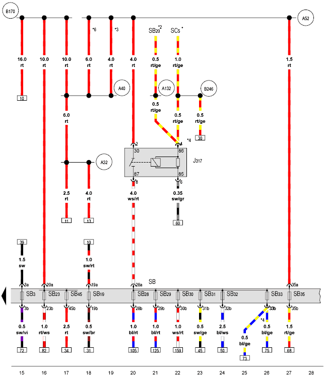
Diagram 2 is a continuation of the previous diagram.
The horizontal line now starts at 15. In this diagram, the fuse box (SB) in the dashboard and a relay (J317) are visible. 00
In the top left, there is a red wire with reference 10. If we follow this reference to the (previous) diagram, we come to fuse 3 in fuse holder A. The positive, therefore, originates from the fuse holder on the battery. Via the positive splice (B170), this positive connection is connected to several other positive splices (A40, A32, and A52). The positive splices are connections where multiple positive wires are connected together. 00
The positive also reaches relay J317. Terminal 30 of this relay is always powered, regardless of whether the ignition or engine is on or off. Terminal 86 is powered via fuse SB20 or SC5, depending on the model year. When this relay is activated, the voltage is passed through terminal 87 to the fuse holder SB. The fuses SB28 to SB33 are then supplied with voltage. This relay is responsible for powering multiple components that only receive power when the relay is activated. But which component ensures this? We look at reference 60 on terminal 85.
VAG Diagrams: Connector Codings and Pin Assignments:
In the previous diagram, we searched for the component responsible for switching relay J317 on and off. We found the diagram that is being referred to. At number 60 on the horizontal line, we look up and find reference 22. This black/gray (sw/gr) wire from both diagrams is, in fact, a single wire connection. We arrive at control unit J623 (engine control unit). This means that the components powered in the previous diagram via fuses SB28 to SB33 are indirectly switched on and off by the engine control unit.
The related components connected in this manner are: the lambda probe heater element, the fuel dosing valve, the boost pressure solenoid valve, the EGR cooler switch-over valve, the glow plug ECU, the brake light switch, and the clutch position sensor. If the ignition is off, the relay is not energized, and no power is present on these components.
On the engine control unit J623, several connectors are present. One of them is the T94. This is a 94-pin connector (thus, 94 possible connections from 1 to 94, not all of which need to be occupied). All wires connected to the ECU in this diagram are connected to connector T94. Each wire has a number, for example, /26. This means that this wire is in position 26 of connector T94. We note this as T94/26. If we measure with a breakout box, we search for connection T94/26 in the overview.
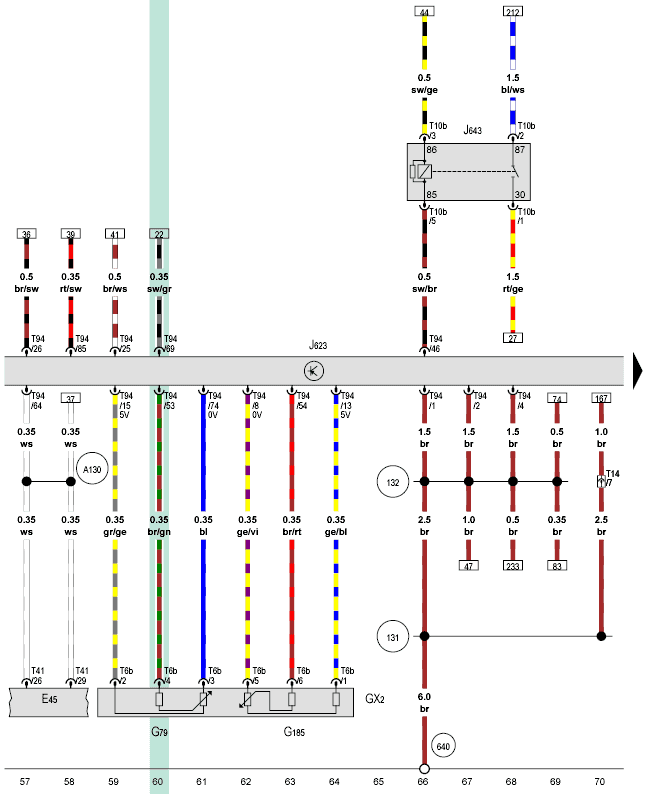
Besides the connections on the ECU, each component also has its own connector coding and pin assignment. We search for the component codes G79 and G185 in the previous diagram. These are the codes for the accelerator pedal sensors. The two sensors are housed in one assembly. A connector with six connections is attached to the housing. The coding of the six-pin connector is T6b. The connections are 1 to 6. 00 The far-left connection has the code T6b/2. This connection is linked with a gray/yellow wire to T94/15 on the engine control unit. The function of each wire and connection will be discussed in the next paragraph.
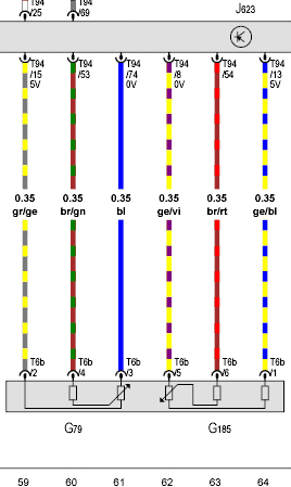
VAG Diagrams: Positive, Ground, and Signal Wires of an Active Sensor:
The following diagram shows a section with the accelerator pedal sensors G79 and G185 from the previous diagram. We see six connections in the housing: three for G79 and three for G185.
Pin 2 of connector T6b is connected to T94/15 on the engine ECU. Here it states: 5V mentioned. This is the positive connection of the active sensor. The blue wire on pin 3 of the sensor is the ground wire (0 volts). The middle (brown/green) is the signal wire.
The engine ECU applies a voltage of 5 volts to the accelerator pedal sensor, which is an application of the potentiometer. Depending on the position of the accelerator pedal, the electronics send a voltage to the ECU. The arrow on the resistor (the wiper) moves up or down when operating the accelerator pedal.
- Arrow down: Signal voltage high. 00
- Arrow up: Signal voltage low.
- The higher the arrow is positioned, the more voltage has been absorbed through the resistor before it reaches the wiper.
The interface electronics in the ECU translates the height of this signal voltage to the accelerator pedal position. The second sensor is built-in for safety. The wiper here is reversed; this means that the signal voltage is inversely proportional: if the voltage at sensor 1 rises, the voltage of sensor 2 will drop. If this is met, the ECU accepts this signal.
The next diagram deals again with active sensors. In this case, the sensors do not each have their own power wires, but it is distributed.
In this diagram, we see, among other components:
- G247: Fuel Pressure Sensor;
- G581: Charge Pressure Controller Position Sensor;
- G40: Hall Sensor.
Let’s first look at the fuel pressure sensor. On pin 2 of connector T3o, this sensor is connected by a yellow/gray wire to T60/40 on the engine control unit. We can assume that this is the signal wire. Besides this signal wire, the sensor must also be provided with positive and ground wires. We examine pin 1 of connector T3o. This brown wire converges with the brown wires of the other sensors at designation 85. This number is visible on both the left and right of the horizontal connecting line.
In the legend, this is labeled as “ground splice 1 cable bundle engine compartment.”
The same almost applies to the positive wire: the positive wires are designated with D141 (positive splice 5v engine compartment).
If we are dealing with a malfunction, we are interested in where the actual positive and ground wires originate from. We follow the references.
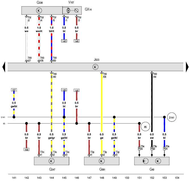
The positive splice (D141) and ground splice (85) are found in the next diagram. These positive and ground wires converge at the connector terminals T60/10 and T60/51 of the engine ECU. 00
Component GX5 is the EGR solenoid valve. The G212 and V338 are the position sensor and the electric motor of the EGR valve.
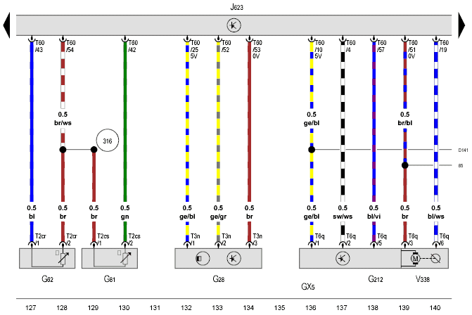
VAG Diagrams: Shielded Wires:
A magnetic field can cause interference on a sensor signal. For some signals, this can negatively affect the engine’s functioning. To reduce the impact of this interference signal as much as possible, the signal wire is wrapped by a separate wire that is grounded by the ECU through filter circuits. Shielded wires are commonly applied to the signal wires of:
- Throttle Position Sensor;
- Inductive Crankshaft Sensor;
- Knock Sensor.
In the diagram, we see that the wires from component G61 (knock sensor) are circled with a dotted line. This circle is connected by a black 0.35 mm² wire with position 38 of the ECU.
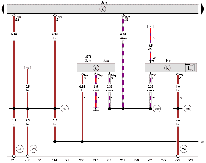
VAG Diagrams: Networks:
The following diagram shows a LIN-bus network of a master (J519 – control unit electrical installation) and two slaves. The LIN-bus is a single-wire communication system. This means that communication between the different control units occurs via only one wire.
- G578, G273, G384: Alarm System Sensors, Tilt Angle and Interior Monitoring. The three sensors are housed in one enclosure;
- H12: Alarm Horn.
The master communicates with the slaves via the vi/ws (violet-white) LIN-bus wire. In the diagram, this wire is labeled with the number: B549.
The power wires of the sensors run via various references to the positive and ground points in other diagrams. How to look this up is described in one of the first paragraphs on this page.
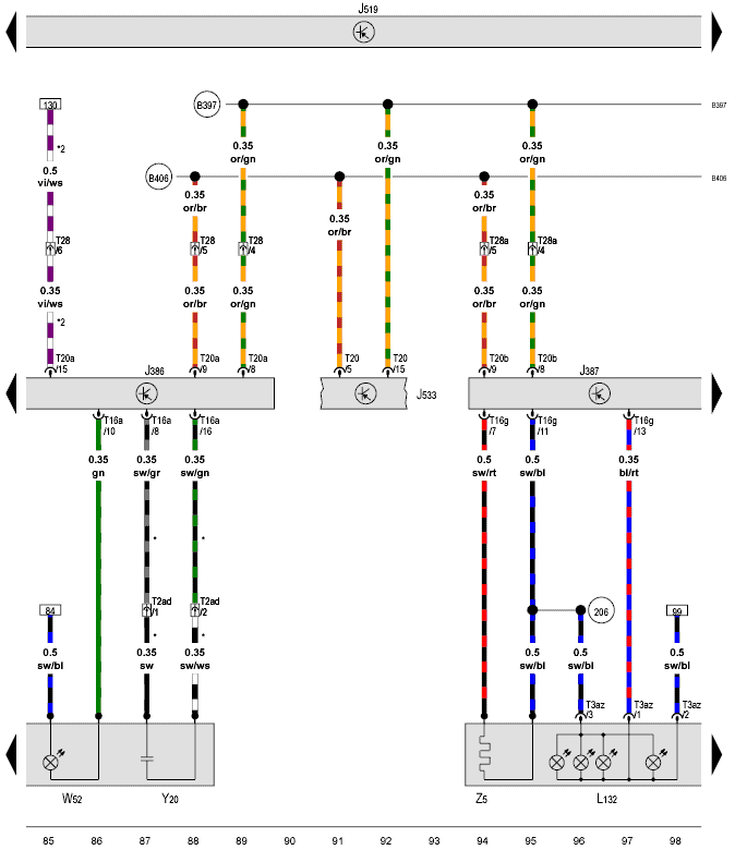
The CAN-bus system is shown in the next diagram. Communication occurs via two wires: CAN-high (B397) and CAN-low (B406).
The control units shown are the:
- J386: Driver’s Door Control Unit;
- J387: Passenger Door Control Unit;
- J533: Gateway.
The door control unit J386 is connected to the other control units in the network via the CAN-bus wires. Besides the CAN-bus, a LIN-bus wire is also visible on pin 15 of this control unit. The LIN-bus wire is connected to the side mirror.
If we want to look up all the control units of this bus system, we look at what the horizontal lines of B397 and B406 are connected to. These lines run through ten more diagrams, where one or more control units are connected in parallel to these CAN-bus wires on each diagram.
Assignment: Reading VAG Diagrams:
By reading and understanding the above explanation, you become familiar with the symbols, abbreviations, and references of the VAG diagrams. The following assignment provides an opportunity to practice with the knowledge you have gained. Below you will find an educational assignment on schematic reading, which includes a complete diagram of a comfort system, a questionnaire, and an answer sheet. Of course, try to answer the questions first before viewing the answers!

HGS Data Lighting Diagram:
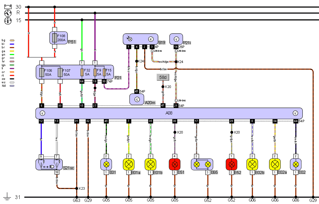
The electro diagram below is sourced from HGS data and is of a BMW. Below the diagram, the legend shows the meanings of the numbers and abbreviations. 00The top and bottom lines in the diagram are the battery positive and negative. R stands for: Radio Position; this is also known as terminal 75. Below is terminal 15: voltage is present here when the ignition is switched on.
The positive connections 30, R, and 15 are connected to the fuse box P21 with red (rt), green (gn), and lilac (li) wires. From the fuse box, four wires run to control unit 08 and to the light sensor (B19).
The steering column switch S21sc is operated by the vehicle’s driver. The switch’s position is communicated to the ECU. The pins 9 and 7 of the switch are connected by a blue and white wire to pins 12 and 13 of the ECU. 00
In the ECU, the switch’s position is translated into lighting control. Each lamp has its own connection to the ECU. When the driver switches on the parking lights, the ECU supplies power to the following lamps: E01, E02, E51, E52, E65, and not to forget the dashboard lighting: 58d.
Further seen is LIN-bus communication between the light module control unit, light sensor, and the combination instrument panel.
There are several ground points. The locations of these ground connections can be traced in the legend.
Legend:
F108 Maxi-fuse 200 A
5A Fuse 5A (3)
15 Ignition On – 15
30 Battery Voltage – 30
31 Ground – 31
50A Maxi-fuse 50 A (2)
58d Instrument Lighting
A08 Light Module
A20m ECU Multifunctional Unit
B19 Light Sensor
E01 Parking Light Left
E01a Low Beam Lamp Left
E01b High Beam Lamp Left
E02 Parking Light Right
E02a Low Beam Lamp Right
E02b High Beam Lamp Right
E51 Taillight Left
E52 Taillight Right
E65 License Plate Lighting
G05 Ground at Left Headlamp (4)
G06 Ground at Right Headlamp (3)
G29 Ground on Driveline Tunnel (2)
G52 Ground in Trunk R (2)
G63 Ground under Driver’s Seat
L LIN-bus (3)
P21 Interior Fuse Box
P21i Combination Instrument
P51 Main Fuse Box Trunk
R Radio Position – R
S21sc Steering Column Switch
X20 Steering Column Connector (3)
X23 Left Dashboard Back Connector
X24 Right Dashboard Back Connector (2)
HGS Data Wiper Diagram:
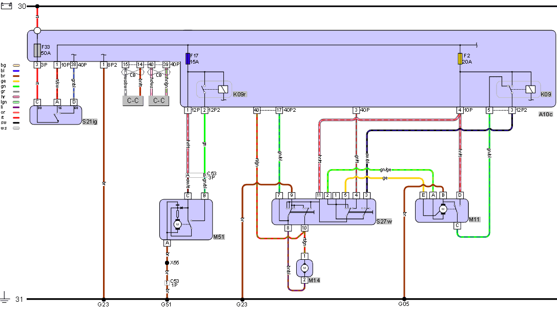
The diagram below shows the wiper system of a Smart. The wiper motors are switched on and off via the relay. The relay K09r is for the rear wiper motor and is grounded by the control unit. The switch is not in direct connection with the relay; the control unit activates the relay in:
- the switch position 1 (interval) position 2 (constant speed) or position 3 (high speed);
- during an activation with diagnostic equipment, for instance, during an actuator test.
For the rear wiper motor, the black/red wire on pin C is the positive wire; via the fuse (F17), this connection is linked to terminal 15 of the ignition switch. Thus, when the ignition is on, pin C is always powered.
The brown wire is the ground wire; via connection X55 in the tailgate, this wire is connected to ground point G51, located on the left in the trunk.
On pin B, a green/blue wire is connected to terminal 87 (not visible in the diagram) of the relay (connection 1). The main current is switched on and off at this point. 00
When the wiper switch S27W is activated, the ECU grounds terminal 85 of relay K09r (output control current). The relay is energized at that moment. Less than a second later, the activation stops. The wiper motor completes its movement thanks to the contact plate. It remains in the zero position until the relay is activated again for a second. This is called the interval. Between each forward and backward movement of the wiper arm, there is a small pause. The time between activations can often be set on the wiper stalk.
The switches in the wiper motor are the conductive contact plate and the slip contacts in reality.
The front wiper motor (M11) operates in a similar manner. Connection B is the ground connection, A position 1 (low position and interval), E position 2 (high speed), and D to move the motor via the conductive contact disc back to the zero position.
Legend:
#1 Resistor
#2 Diode
15A Fuse 15 A
20A Fuse 20 A
30 Battery Voltage – 30
31 Ground – 31
50A Maxi-fuse 50 A
A10c Central Electrical Installation Interior
C-C CAN-bus comfort (2)
C53 Connector Left D-pillar (2)
CB CAN-bus (2)
G05 Ground at Left Headlamp
G23 Ground Behind Dashboard L (2)
G51 Ground Trunk L
K09 Relay Front Wiper Motor
K09r Relay Rear Wiper Motor
M11 Front Wiper Motor
M14 Windshield Washer Pump
M51 Rear Wiper Motor
S21ig Ignition/Start Switch
S27w Wiper/Washer Switch
X55 Rear Hatch Connection