Subjects:
- Preface
- Colors
- H4 and H7 lamps
- Reflectors
- Light image of the low beam
- American headlight
- Headlight height adjustment
- Measuring and Connecting Headlight Wiring
- Repair Headlight Wiring
Preface:
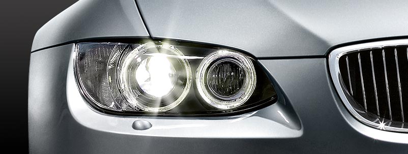
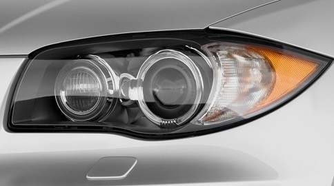
The headlights provide the lighting at the front of the car. Some cars have all the lights in one housing (like the car in the picture below) and others have multiple units. The mandatory front lighting consists of: parking lights, dipped beams, high beams, turn signals and possibly fog lights and daytime running lights. For the lamps, a choice is made between a incandescent lamp, halogen lamp, xenon and/or LED.
Colors:
The city lights must be yellow or white when lit. Become Default halogen lamps applied. Lamps with a blue paint layer are intended to emit as white as possible (eg with xenon). Dipped and main beams must be yellow or white. xenon lamps often become blue/purple in color, but on the headlight adjustment device the light image is often still just white. Other colors are not allowed.
Front turn signals may be orange, yellow or white. Fog lights have the same requirements as the low beam and high beam; they should be yellow or white in color.
Daytime running lights may only be white in color. In America the “daytime running lights” are often orange in color and are constantly on with the main lighting switched off. In the Netherlands this is prohibited and the orange lamps must be replaced by white ones. If that is not possible, they should be disabled. This often presents another problem when the daytime running lights and turn signals are combined; then the only solution is to mount white lamps. White flashing lights are allowed.
Xenon lamps are often equipped with headlamp washers in the headlamp housing or in the front bumper. This is to prevent stray light from eg dirt and insects on the headlight glass.
H4 and H7 lamps:
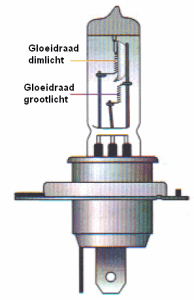
The most commonly used types of lamps are the H4 and H7 lamps. An H4 lamp is shown at the bottom left. This lamp has two filaments one behind the other; one for low beam and one for high beam. When the dipped beam is switched on and the driver signals (or the main beam is switched on), the dipped beam switches off briefly.
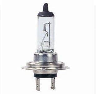
An H7 lamp is shown at the bottom right. This lamp has only 1 filament; this one is only for low beam. So a separate bulb is needed for the high beam.
The H4 bulb is a lot thicker than the H7 bulb, so they can't be accidentally swapped in the headlight housings. The H4 lamp also has three connections on the plug and the H7 lamp has two.
Reflectors:
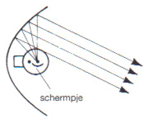
Low beam reflector:
The dipped beam lamp shines upwards, against the top of the parabolic reflector. This reflector reflects the light back at a certain angle. These rays of light must, of course, be directed downwards. There are people who mount the light in the headlight the other way around (by force, because actually it is not possible). The light rays then go up and blind all oncoming traffic.
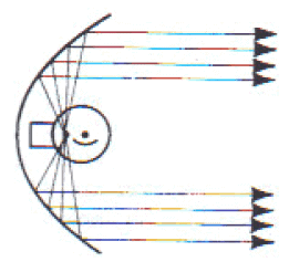
High beam reflector:
The high beam bulb radiates in all directions, up and down, left and right. The reflector reflects the light rays straight forward, creating a large beam of air. The light output is now maximum, but very annoying for oncoming traffic who are blinded.
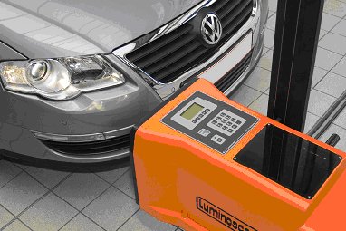
Light image of the low beam:
The light image of the car is measured during a major service and MOT and adjusted if necessary. An adjustment device is placed in front of the headlight, which contains a screen that measures the incidence of light. The headlight can be adjusted on the basis of the light image in the adjustment device by adjusting the adjustment mechanisms in the headlight. The fog lamps can also be adjusted in this way, but this is usually only done after disassembling, disassembling or replacing the fog lamp units.
Four different light images are shown below (of which light image 1 as an example of a high or low adjustment). The other three light images are common in practice. If a headlamp is rejected for the MOT on the poor light image due to weathered headlamp glasses or reflectors, many people do not know how this is determined by the inspector. These images make that a lot clearer. There is also a borderline case, which can just pass the inspection.
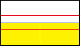
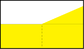
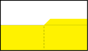
Light image 1:
This is just the horizontal line. The black dotted line indicates how far the light (yellow part) is allowed to reach. This is often between 1,0% and 1,5% for cars without xenon and about 2% for cars with xenon. The top red line shows where the light image would be if the headlights were set to 0% (too high). The bottom red line indicates a too low light image (eg 3%). It is also possible that in that case the adjusting motor is set too far down, which can be adjusted in the interior. It must always be turned to 0 prior to adjustment.
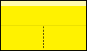
Light image 2:
A perfect light image. A good height, with the arc on the right that shines towards the verge. This is always the case with cars driving on the right side of the road. On English cars this arc is directed to the left. That is why there are often stickers on the headlights of English cars when they go to another country. This is purely to shield this arc, to prevent dazzling oncoming traffic.
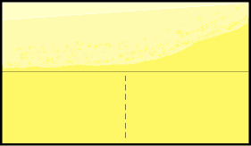
Light image 3:
In cars with weathered headlight lenses or weathered reflectors, the light pattern often looks like this. There is a lot of scatter light; there is a lot of light at the top of the dividing line. Sometimes it is so bad that no dividing line is visible anymore. In principle, the headlight radiates in all directions, while the light output (including visibility) is also minimal. It is up to the judge to determine whether it is rejection or whether it is still admissible.
If there is still a horizontal dividing line (as in this image) it might just be approved.
Light image 4:
If the lamp is mounted the other way around in the headlight, the light does not shine downwards, but upwards. That can be clearly seen in this image. See the image to the right.
American headlight:
American headlights differ from European versions. Often an orange reflector or extra orange lighting is built in, which is not on the European version. Also, the flashing lights are on constantly (if the flashing lights are not lit, other amber lights have been added to the car). The orange lamps switch on as soon as the car is switched on (just like daytime running lights). This is not allowed in the Netherlands. The orange lamps may only be used as a flashing light and must not be constantly lit. Not even if they are only controlled for 50%. This is MOT rejection and reason for a fine at a traffic control.
Another difference between the headlights is the light image. Contrary to European guidelines, the light image of an American headlight runs horizontally on the right side of the light image. The light image rises slightly from the center and then the line runs horizontally to the right. The headlight now shines more straight ahead than it shines in the verge. This can sometimes cause a problem with imported cars. In principle, this is not according to European requirements, so the judge could see this as a rejection. This also purely depends on how high the line on the right side is compared to the left side.
Headlight height adjustment:
The headlamp height is adjustable so that it can be lowered when the vehicle is loaded. The tilt motor, also called the mirror adjustment motor or adjustment motor, ensures that the reflector in the headlamp tilts vertically about its axis.
The three systems to adjust the headlight height are:
- Static height adjustment. The driver operates the adjustment by means of a button on the dashboard.
- Dynamic height adjustment. The height adjustment reacts to body movements.
- Semi-static height adjustment. The sensors on the suspension arms register the vehicle's load. For example, when the vehicle is loaded at the rear, the rear of the vehicle lowers and the headlights shine upwards. In that case, the semi-static height adjustment lowers the headlights.
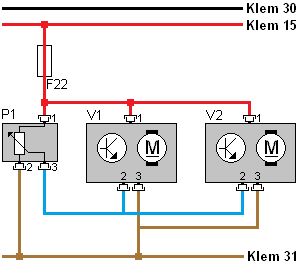
The diagram on the right is of the static headlamp height adjustment. The diagram is of the “waterfall” type with the plus (terminal 30) at the top and the mass (terminal 31) at the bottom. The circuit is protected by fuse F22. The potentiometer (P1) is the adjustment knob that can be turned by the driver. The potentiometer is a variable resistor and has a plus (pin 1), ground (pin 2) and a signal wire (3). The voltage on the signal wire depends on the position of the wiper of the potentiometer. The bishop is indicated as an arrow on the resistance. The voltage arrives at the adjustment motors 1 (V1) and 2 (V2) via the blue wire. The electronics of the adjustment motors (indicated by the transistor symbol) will adjust the adjustment motors in the desired position.
In the diagram, only a positive wire, ground wire and signal wire are shown for an adjustment motor.
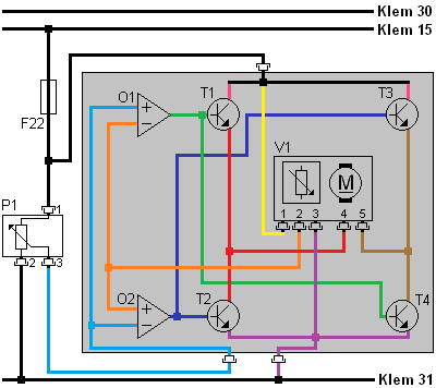
The control unit reads the position of the adjustment motor and then controls it to set it in the correct position. The diagram below shows what actually happens in the control unit. The diagram and the text refer to the left adjustment motor (V1).
The control unit contains two opamps and four transistors, which in this case are designed as a differential amplifier. Depending on the voltage difference that arises between the potentiometers in the dashboard and in the adjustment motor, the transistors are controlled by the opamps. This voltage difference arises, for example, when the driver turns the adjusting wheel (P1) downwards. The bishop on the variable resistor takes a different position. As a result, more or less voltage will be lost in heat. This increases or decreases the voltage on pin 3 of P1. This voltage enters the two opamps (O1 and O2) via the blue wire. The opamps measure the voltage difference between both potentiometers (P1 and V1), so between the blue and orange wires.
- In peace: When the voltages on the blue and orange wires are equal, the system is at rest.
- Adjusting wheel turned down: Transistors T1 and T4 are turned on by opamp O1 when the voltage across the blue wire is higher than on the orange wire. The adjustment motor is powered on pin 4 via the red wire (via T1) and ground on pin 5 via the brown wire (via T4). This causes the adjustment motor to rotate clockwise until the tension of its potentiometer has reached the same voltage as the potentiometer in the dashboard (P1). When there is no longer a voltage difference between the wires, the opamp will no longer apply voltage to the output.
- Adjusting wheel turned up: If the adjusting wheel is turned the other way by the operator, the tension on the orange wire will be higher than on the blue wire. Now opamp O2 puts a voltage on the output. Transistors T2 and T3 now conduct. The adjustment motor now turns counterclockwise, i.e. in the other direction, because the polarity has been reversed compared to the previous situation. The drive stops again the moment the opamp no longer measures the voltage difference between the runners of the potentiometers.
Measuring and connecting headlight wiring:
The headlight wiring harness can be damaged after a collision, improper installation that causes the wiring to become pinched, or the wiring harness rubbing against something. The wiring can be damaged or even break. To repair the wiring, in most cases the same color cables can be reconnected. A mechanic should be able to figure out which wire has which function by reading the schematic and taking measurements. At that point, the wires on the vehicle side can be connected to the headlight wiring. This knowledge and skills are part of the practical exam for first mechanic.
In the below electric scheme shows a lighting system from the front of a vehicle. The legend is shown to the right of the diagram. The diagram is of the “waterfall” type, with the pluses above (terminal 30 and 15) and the mass below (terminal 31). The schematic shows several switches connected to a control unit (A20). This ECU switches on the indicators (E5 and E6), as well as the relays for the low and high beam lamps. The side/parking light is switched on and off directly by the lighting switch (S21). Furthermore, the headlight adjustment motors (M01 and M02) are shown, which rotate up or down on the basis of the signal from the adjusting wheel containing the potentiometer.
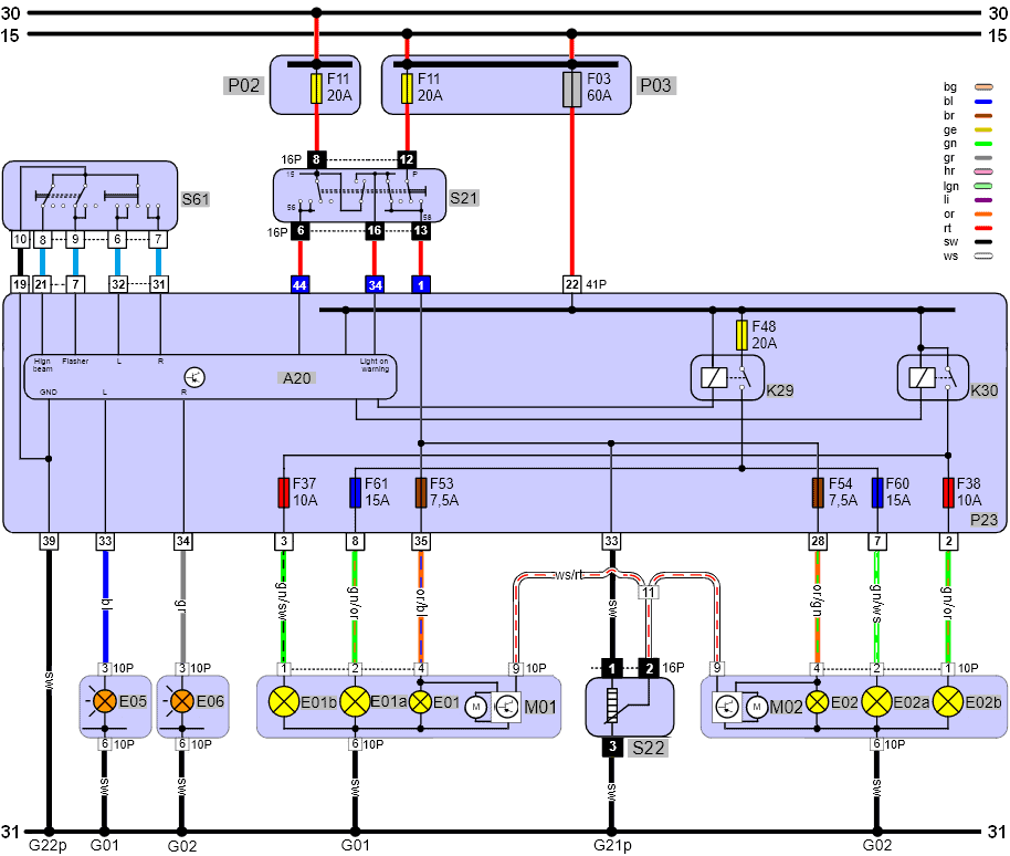
P02: fuse box for terminal 30;
P03: fuse box for terminal 15;
S61: steering column switch (blinker and high beam);
S21: Light switch (city and main lighting)
A20: Control unit;
K29: Low beam relay;
K30: High beam relay;
E05: Flashing L;
E06: Flashing light R;
E01B: High beam L;
E02B: High beam R;
E01A: Low beam L;
E02A: Low beam R;
E01: Parking light L;
E02: Parking light R;
M01: Motor height adjustment left;
M02: Engine height adjustment right;
S22: Headlamp level adjustment wheel
G01: ground point lv;
G02: ground point rv;
G2*p: ground point interior
As already described above, a mechanic should be able to connect the headlight wiring by reading the schematic and taking measurements. To clarify this, below is a step-by-step plan to connect the (cut) wires on the vehicle side (often one color, in this case red) to the colored loose wires of the headlight.
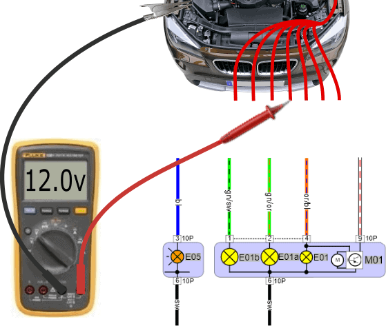
Parking light / parking light:
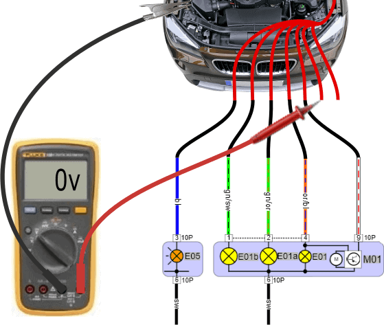
First we check whether the voltage on all wires – originating from the car – in relation to ground is 0 volts when the lighting is switched off.
In the legend we saw that the code E01 of the parking light is on the left side of the headlight. With the voltmeter we look for the positive wire of this lamp.
- Voltmeter ground wire: connect to a good ground point, preferably with an alligator clip around a ground point intended for the battery charger;
- Plus wire: One of the six wires has been changed from 0 volts to the on-board voltage (12 to 14 volts). We measure the red wires one by one and look for the relevant wire. To check, the side lights can be switched off and on briefly to see if the voltage varies between 0 and 12 volts.
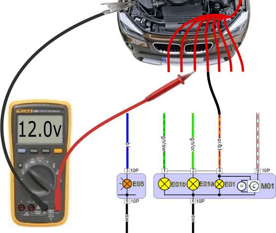
Low beam:
We connect the parking light from the previous measurement to the or/bl (orange/blue) wire and switch on the low beam. Now the voltage of two wires is 12 volts: the side light (stays on) and the wire of the low beam. We are looking for this thread.
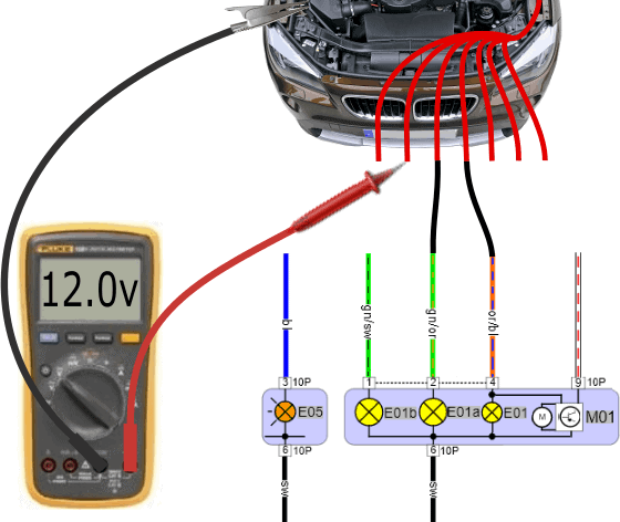
High beam:
After the wire from the low beam is connected to the gn/or (green/orange) wire, we switch on the high beam. One of the remaining red wires has become 12 volts. We connect this wire to the gn/sw (green/black) wire of E01b (high beam).
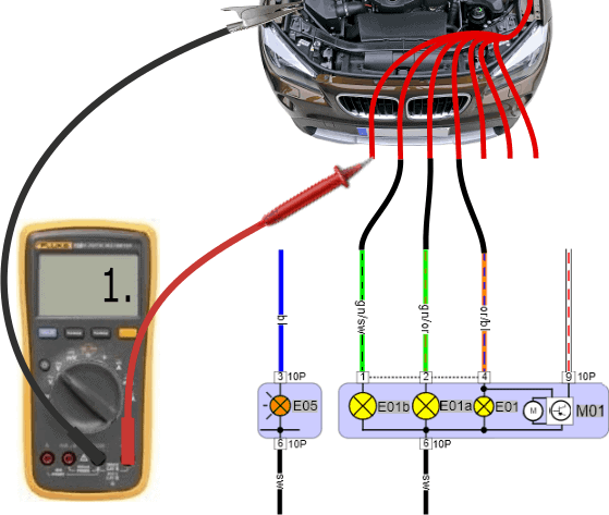
Flashing light:
A voltmeter may be too slow to measure the alternating voltage between 0 volts (off) and 12 volts (on) when the flasher is turned on:
- The voltage display on the display may jump;
- The display may show “infinite” or “overload”.
The square-wave voltage could be checked with an oscilloscope, but this is actually not necessary. When switching the flashing light on or off, we see a voltage change in the display, giving us enough information that we are measuring on the right wire. We connect this wire to the bl (blue) wire of E05 (flashing light).
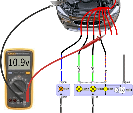
Height adjustment:
A lower voltage will be measured on one of the wires after switching on the parking or dipped headlights than the positive wires of the lamps. In this case we measure 10,9 volts. With a deviating voltage value, we almost always have to deal with the signal wire for the headlight adjustment motor.
In the interior (dashboard, steering column, instrument panel) is the adjustment wheel or digital button to move the headlamp adjustment motors up or down. In position 0 (headlights are in the extreme position up) the voltage is often high. When we turn the adjusting wheel to position 2 or 3, the voltage on the signal wire to the adjusting motor drops: this commands it to move downwards. The voltage can drop to 3 or 6 volts in position 7.
We then connect the wire for the height adjustment to the ro/wi (red/white) wire. Unfortunately, the schematic lacks color coding.
Mass (1):
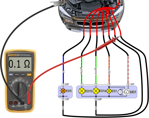
Until now, all positive wires have been connected, but without ground wire / wires the lamps and the servomotor do not function yet. The voltage on the remaining wire has remained 0 volts during all measurements. To make sure that the wires on which you are measuring 0 volts are a ground wire, we perform a resistance measurement. This measurement is shown below.
Mass (2):
The resistance on the red wires to the ground point on the body is both 0,1 ohms. It is possible that the resistance value is slightly higher, eg 5 ohms. Now that we are sure that the last two red wires are attached to the body, we connect them to the black wires from the headlight.
- Vehicles where the flashing light is in a different unit or part of the headlamp often have two separate plugs (as shown in this diagram). Both plugs have a ground wire. Often these two ground wires are connected to the same ground point, so it doesn't matter if they are swapped;
- If we have a vehicle with the flashing light in the lighting unit, then there is a ground weld in the headlight where several ground wires come together and come out as one ground wire.
We always carry out the resistance measurement last. The reason is that a switched-off lamp is sometimes grounded on both connections (plus and minus) by the switch. When one starts with the resistance measurement, a mass is measured on several plus wires. Only when the lamp is switched on does the mass change into a plus.
Massage Switched H4 Bulb:
In this section we have so far only discussed the plus-switched H7 lamp. We recognize this by the fact that the low beam and high beam lamps receive a plus (12 volts) on their own wire to make the lamps burn.
We could also be dealing with a ground switched H4 lamp. The following three diagrams (right and below) relate to a disabled H4 lamp containing:
- E01a: low beam;
- E01b: high beam;
- S21: lighting switch;
- S25: toggle switch between low and high beam;
- Ins: high beam indicator light in the instrument panel.
With a properly functioning lighting system, we measure the on-board voltage (around 12 volts) on both the plus and minus connections when switched off. The voltage difference across the lamp is now 0 volts (on the plus and minus). There is now no current flowing through the filament. The lamp is off.
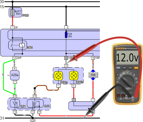
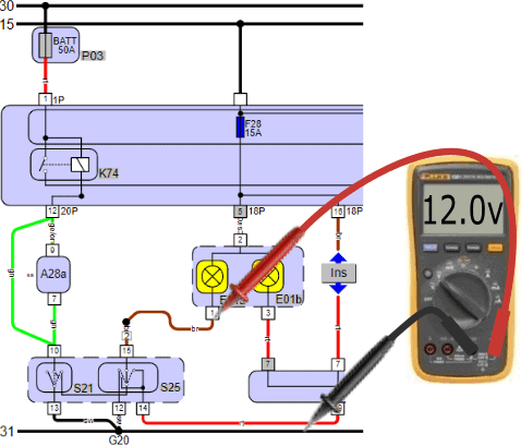
The switch S21 (lighting switch) supplies the adjacent switch (S25) with a power supply when the lighting is turned off. When switching on eg the low beam, S21 and S25 both switch to ground. The driver can use S25 (usually the turn signal lever on the steering column) to switch the low beam or high beam to ground. One of the two lamps will light up.
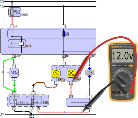
H4 Bulb Enabled:
The supply voltage of the lamps is again 12 volts. The minus connections of the lamps (brown low beam, red high beam) are switched to ground via switch 25.
- Dipped beam: when the dipped beam is switched on, the voltage on pin 1 of the lamp decreases with respect to ground from 12,0 to 0,4 volts;
- High beam: When the high beam is turned on, the voltage on pin 3 drops to 0,4 volts.
Note: When the low beam is on, the high beam is off. The moment we measure 0,4 volts on the ground connection of the low beam, the voltage difference across the high beam is 0 volts (pin 3 then reads 12 volts). This is also the case with the low beam: when the high beam is on, the voltage difference across the low beam is 0 volts. In short: if one is on, the other is out.
We are talking about a ground switched H4 lamp, but we are measuring 0,4 volts at the ground connection. This is because there is a resistor in the switch that consumes the remaining 400 mV. When repairing and connecting the wire, measure this with the voltmeter, not the ohmmeter!
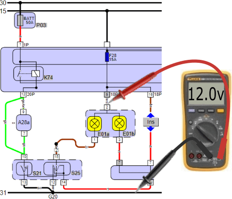


In the diagram we see under E01b a coupling point to which INS (instrument panel) is also connected. The instrument panel has a connection between the plus and minus of the high beam bulb. The moment the high beam lamp lights up (on pin 3 we measure 0,4 volts), the high beam indicator light in the instrument panel is also switched to ground. The indicator light comes on at the same time as the high beam. When switched off, the voltage difference across the indicator lamp is also 0 volts (12 volts on the plus and 12 volts on the minus), so that no current flows through it.
Repair headlight wiring:
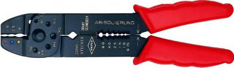
A repair can take place by connecting the wires, with the iron plugs (A) at the end, in socket blocks (B and C) and sliding them together last. The connector blocks shown are fine for use in the interior, but under the hood the uninsulated connectors are subject to moisture, etc. Of course, insulated plug connections must be made here. The principle is the same, and the illustration serves as an example.
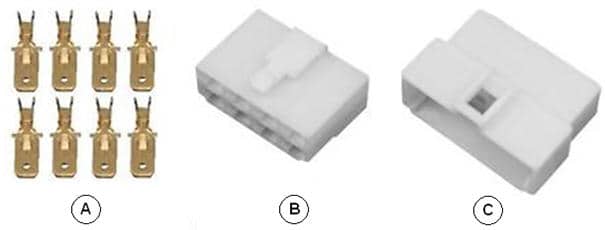
The iron plugs should be pinched on the wire that has been stripped about 1 mm; the copper wire should not be longer. We insert the end of the wire into the iron plug and we pinch the plug on the wire with a special AMP/cable shoe pliers (shown) or a torque wrench.
To make it easy for yourself when connecting, you can make a simple drawing showing the plug positions 1 to 8 and the lamps / adjusting motor in the headlight.
In this example, the right turn signal (R) is connected to pin 2, the parking light / parking light (58R) to pin 5, the servomotor to pins 6 and 7, high beam (56a) to pin 7, low beam (56b) to pin 4 and the ground (31) on pin 3.