Topics:
- Identify and install sensors for the engine management system
- Crankshaft position sensor
- Trigger wheel
- MAP sensor
- Coolant temperature sensor
- Oxygen sensor
Identify and install sensors for the engine management system:
The engine management system requires several sensors. Sensors act as the “input” of the system. Sensors convert a physical quantity into an electrical signal that can be processed by a computer, in this case, the MegaSquirt.
During the assembly process of the MegaSquirt, consideration must be given to the components to be mounted on the engine, as the configuration of the MegaSquirt may vary accordingly.
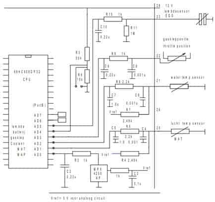
The image shows the different sensor circuits in which these components are located. The incoming signals shown in the figure come from the oxygen sensor, throttle position sensor, coolant temperature sensor, and intake air temperature sensor.
In addition to the sensors, the schematic also contains several resistors and capacitors. The composition of these components forms filters; these filters are used to capture interference and noise. If the sensor signal is distorted by noise, it can have major consequences for the operation of the actuators, and thus also for the functioning of the engine.
Crankshaft position sensor:
An important input for the engine management system is the engine speed.
The engine speed is measured using a crankshaft position sensor and a trigger wheel. The crankshaft position sensor has two important functions:
- Based on the frequency of the signal, the engine speed can be determined;
- The missing tooth in the trigger wheel indicates the crankshaft position in which the pistons of cylinders 1 and 4 are a few degrees before TDC.
Engine speed affects the control of the injectors and ignition. The missing tooth in the 36-1 trigger wheel is important for determining the ignition and injection timings. A Hall sensor, rather than an inductive pickup, is chosen to be used as the speed sensor. An inductive sensor generates an AC voltage that must be converted to a DC voltage within the MegaSquirt controller. A Hall sensor generates a square wave that is amplified to a voltage of 5 or 12 volts using an internal or external pull-up resistor, making the Hall sensor more suitable for forming a reliable signal. This choice must be made prior to assembling the MegaSquirt, as both sensors require different circuit configurations.
Trigger wheel:
The crankshaft position sensor measures a change in the air gap of a trigger wheel mounted on the engine. However, on the Land Rover engine, there is originally no crankshaft position sensor and therefore also no trigger wheel. The trigger wheel had to be mounted afterward. Much thought went into the location and position of the trigger wheel. Options included:
- A disc with 36 teeth attached to the outside of the crank pulley using a clamp or bolt connection.
- Modifying the existing crank pulley by machining teeth out of the pulley.
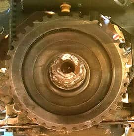
It is common to use a 36-1 or a 60-2 trigger wheel. The trigger wheel with 60 teeth is mainly used for larger diameters. The 36-1 is suitable for use due to the tooth width. It is crucial that the trigger wheel has minimal runout. A runout means a change in the magnetic field between the sensor and the teeth of the trigger wheel, which can adversely affect engine operation. This must obviously be avoided. Therefore, modifying the existing crank pulley was preferred. The outer edge of the existing crank pulley has been machined on a milling machine. By removing material, notches have been created. The remaining 36 teeth are used to allow the sensor to measure changes in the magnetic fields. A tooth was ground off for the reference point. The image below shows the modified crank pulley.
At the top of the trigger wheel, right under the sensor, the ground-off tooth is visible. When the crankshaft is in this position, it does not mean that the pistons of cylinders 1 and 4 are at TDC, but that these pistons are 90 degrees before TDC, which corresponds to 9 teeth (360/36). When the missing tooth passes by, the MegaSquirt receives the signal that ignition should soon occur. From that point, it is calculated when the coil should be activated. Under varying operating conditions, the timing of the advance is also determined based on this reference point.
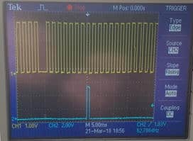
The oscilloscope image (see figure) shows the crank signal (top) relative to the coil’s drive signal (bottom). At the eighth tooth after the missing one, the drive pulse to the coil is formed. During idle, the ignition is advanced by 10 degrees, which corresponds to 1 tooth. This matches the 90 degrees (9 teeth) between the removed tooth and the actual top dead center.
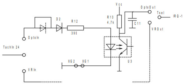
For assembling the Hall sensor circuit in the MegaSquirt, capacitor C11, resistors R12 and R13, diode D2, and opto-coupler U3 need to be installed (see image below). The signal from the Hall sensor enters the schematic in figure 105 at “Opto in.” The signal reaches the so-called opto-coupler via the diode and resistor. This component is indicated with a dashed line. The opto-coupler is a small integrated circuit where the LED on the left side turns on, allowing the phototransistor on the right side to conduct. The opto-coupler can be considered as a switch without mechanical or electrical connections between the control and switching sections.
When the transistor in the opto-coupler conducts, a small current can flow from Vcc to ground. At that moment, there is 0 volts on “Opto Out.” If the transistor does not conduct, there is no current and therefore no voltage drop across resistor R13. The voltage on “Opto out” is then 5 volts.
By using an opto-coupler, galvanic isolation is created between the diode and the phototransistor. Dangerous interference voltages are kept outside the microcontroller circuit, as the breakdown voltage is usually greater than 5 kV.
MAP sensor:
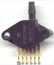
A MAP sensor (Manifold Absolute Pressure sensor) measures the pressure in the intake manifold. The MegaSquirt calculates the amount of air entering the engine using this pressure, engine speed, and intake temperature. On the Land Rover engine, absolute pressure (ambient air pressure) or vacuum will be measured, as it is a naturally aspirated engine that draws in air itself. Engines equipped with a turbocharger have to deal with overpressure in the intake manifold. The measuring range of a MAP sensor is usually between 0.2 and 1.1 bar.
The pressure in the intake manifold, together with the throttle opening angle (measured with the throttle position sensor) and engine speed, can determine the engine load. Due to the absence of a MAF sensor (Manifold Air Flow), the amount of air ingested is calculated based on engine data and the vacuum present in the intake manifold. A MAF sensor was not used because its signal is less reliable since it is not designed for the engine. Tuning the settings to the intake manifold properties is complex, requiring many correction factors.
The applied MPX4250AP MAP sensor is shown in the image. The MegaSquirt circuit board is standardly equipped with connection options for this type of MAP sensor. This sensor is also included as standard in the kit. The amount of injected fuel depends, among other things, on the amount of available air, as there is an attempt to achieve a stoichiometric mixture ratio (14.68kg air to 1 kg fuel). There was a possibility to not use either the MAF or the MAP sensor. The amount of air drawn in would then be determined by an Alpha-N regulation, which looks at the throttle position that is indicative of the amount of available air. However, this is less accurate than a MAP sensor, so this option was not chosen. In this project, the throttle position sensor is only used for acceleration enrichment.
Coolant temperature sensor:
In the classic setup, no temperature sensors are present on the engine block. The engine is equipped with a bimetal that lights up the dashboard lamp in case of high coolant temperature. However, since the engine management system does take into account the temperature of the coolant and intake air, it was decided to install NTC resistors afterward. An NTC resistor has a negative temperature coefficient. This means that the resistance value decreases as the temperature increases. A sensor with a resistance value of 2.5 kilo-ohms at 25°C was chosen as the coolant temperature sensor. The resistance change is greatest in the most critical temperature range. The properties of the NTC resistor must be mapped to calculate an accurate temperature.
The resistance change is greatest within the temperature range of 0°C to 60°C. This is visible in the characteristic path; within this temperature range, there is a resistance drop of approximately 5kΩ, while at T ≥ 60°C, the resistance hardly decreases. In some cases, it is desirable to also measure temperatures above 60°C. To achieve this, at a certain temperature, the internal bias resistor can be switched to a bias resistor of a different value. This yields two NTC characteristics. However, in this project, the coolant temperature is exclusively used for cold start enrichment, which is barely applied above 60°C.
The low temperatures are also the most interesting, where cold start enrichment occurs; the injector is operated longer with a cold engine. Once the engine is sufficiently warmed up (T ≥ 60°C), enrichment is gradually reduced. From T = 90°C, the injection strategy follows the set values in the reference table. The reference table is a standard entered value. External factors, such as cold start enrichment at low temperatures, form a correction factor on this standard value. At this point, the MegaSquirt no longer considers the coolant temperature.
Oxygen sensor:
An oxygen sensor (sensor) is mounted in the exhaust to measure the air/fuel ratio in the exhaust gases. The oxygen sensor has an important role in later stages to “tune” the engine management by populating the AFR and VE tables. In order to gain insight into the ideal mixture ratio and the necessity to enrich or lean the mixture, the stoichiometric mixture ratio, enrichment, and leaning are first defined.
The stoichiometric mixture ratio indicates the ratio between air and fuel where all oxygen from the air is used. This is the case at a ratio of 14.68:1 (rounded to 14.7 kg air to 1 kg gasoline). We refer to this as λ = 1.
The lambda value can vary under different operating conditions:
- Enrichment: λ < 1;
- Leaning: λ > 1.
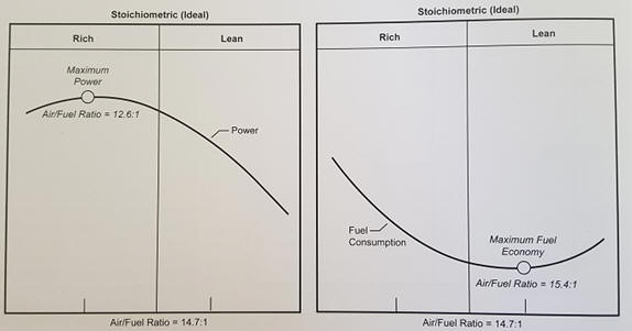
Enriching to λ = 0.8 means a mixture ratio of 11.76 kg air to 1 kg gasoline is applicable. There is thus less air available for 1 kg of fuel. The enrichment or leaning of the mixture must always remain within the explosion limits. Enrichment occurs when more power needs to be delivered by the engine. Additionally, a richer mixture provides cooling. A lean mixture, on the other hand, results in more favorable fuel consumption. The image below shows two graphs displaying maximum power and lowest fuel consumption.
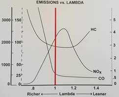
The lambda value not only affects power and fuel consumption but also exhaust emissions. A richer mixture results in lower NOx levels but also higher CO and HC emissions. In a leaner mixture, the fuel particles are further apart, causing combustion to no longer be optimal, resulting in increased HC emissions as well. The image below shows emissions related to the lambda value. When using a catalytic converter, it is desirable for injection to fluctuate between rich and lean. A rich mixture forms CO due to oxygen deficiency, which the catalytic converter uses to reduce NOx. A lean mixture contains excess oxygen, oxidizing CO and HC.
There are two types of oxygen sensors; the switching sensor and the wideband sensor. The MegaSquirt supports both types. However, when setting the VE table, a switching sensor is unsuitable, which is why the choice was made to use the wideband sensor. Setting the VE table involves adjusting the VE values based on the measured AFR. Although the VE values can initially be filled through calculations and largely based on the torque curve, the AFR quickly falls outside the range of the switching sensor. A wideband sensor is a solution due to its large measuring range; it can measure an AFR between 8.0 and 1.4. The mixture composition will generally fall within this measuring range with a running engine, making the wideband sensor suitable for setting the VE table. Tuning without the wideband sensor is practically impossible.
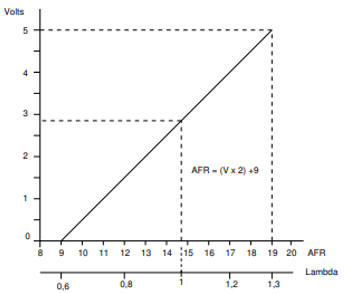
The MegaSquirt does not have an internal lambda controller. When the characteristics of the wideband sensor are known, they can be input into the TunerStudio program in a table. In other cases, a wideband sensor with an external controller is required. The output voltage is linearized by the external controller. The output voltage from the controller to the MegaSquirt ranges from 0 to 5 volts, with a linear relationship between the lambda value and the voltage. The voltage value is converted to a lambda value in the MegaSquirt. The image shows the graph with the linear relationship.
Next: Actuators.