Topics:
- The start of the project
- Engine
- Transmission
- Inspecting, replacing, and adjusting engine components
- Mounting the engine on a mobile frame
- Cooling
- Dashboard and electrical system
- Fuel pump and tank
- Operating the engine in a classic setup
The start of the project:
After deciding to equip an engine with a MegaSquirt engine management system, consideration was given to a suitable engine type. Standard conversion kits with manuals were not of interest. The objective was to use an engine that met the following conditions:
- no previous conversion projects of this engine are known;
- four-cylinder gasoline engine;
- not yet equipped with an injection and electronic ignition system;
- the ability to load the engine.
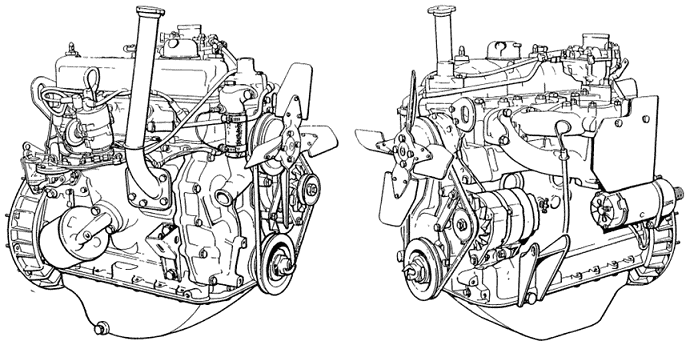
Engine:
The search led to an engine from a Land Rover (series 2A) from the early 1970s. This 2.25 liter four-cylinder gasoline engine with three main bearings was originally equipped with a carburetor and mechanical distributor ignition. The combination of this Land Rover engine and the original transmission was decisive for the choice; a transmission brake is attached to the output shaft of the transmission. The transmission brake, which actually serves as a parking brake, provides the ability to load the engine during operation by engaging this brake.
The engine probably had not functioned for decades. Naturally, it must be reliable enough to run on the engine management system. Therefore, it was necessary to thoroughly inspect and test the engine first. The following objectives were set:
- Inspect, replace, and adjust engine components;
- Mount the engine on a mobile frame;
- Operate the engine in the classic setup;
- Install components for the engine management system;
- Assemble and prepare the MegaSquirt ECU;
- Operate the engine on the engine management system.

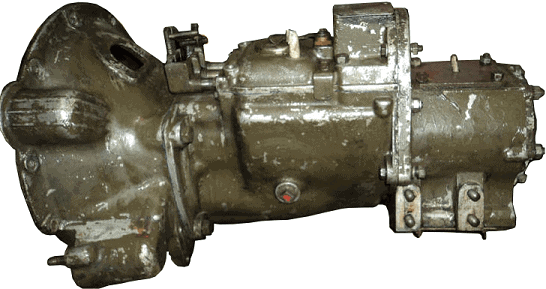
Transmission:
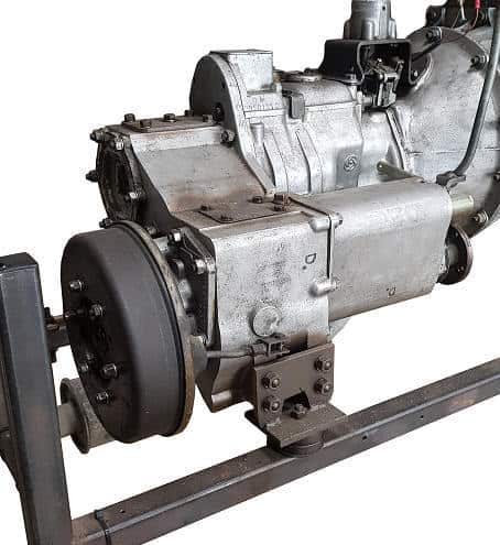
The transmission comes from a military Land Rover. The green color actually reveals it. To later form an – as original as possible – whole with the engine, the green paint was removed. The transmission brake is not present in the photo; it was later mounted on the output shaft according to factory specifications.
Inspect, replace, and adjust engine components:
At the start of the project, it was unclear whether the available engine was suitable for use. Little was known about the engine block, only that the engine had been idle for years. It was unclear whether there were internal parts damaged or even defective – possibly irreparably. In the latter case, replacing the engine with another unit was the only option to continue the project.
To avoid concluding later that the engine would be unusable, it was decided to disassemble and overhaul the engine. Wear patterns of the parts were checked and compared with factory specifications. Parts whose measurements were within these tolerances were reinstalled. Parts that were rejected were replaced. Consideration was given to the purpose for which the engine was to be used; the engine should be rebuilt with as few costs as possible to be sufficiently reliable for the project and use as an educational tool.
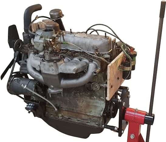
The engine is mounted on the suspension points of the transmission housing on the mounting stand. The engine can be rotated in different positions. This makes both the cylinder head and the oil pan optimally accessible for disassembly work. For the engine to function properly, it is important to take precautions to ensure proper final compression pressure. If the pressure of one or more cylinders is too low, this will result in a poorly functioning, stuttering engine. In that case, adjusting with the newly installed ignition and injection system is difficult, if not impossible.
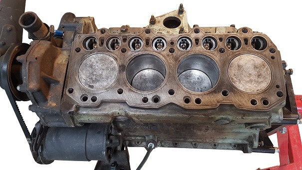
One of the first checkpoints is the pistons and cylinder walls. For a proper check, the pistons needed to be removed from the engine block. After removing the cylinder head and oil pan, the pistons could be taken out. The pistons were checked for ovality and visible wear marks. The piston rings were also checked for wear. Worn piston rings can cause compression loss and oil consumption; both consequences should be prevented by this check. Besides an optical check, the clearance between the piston ring grooves and the piston ring was also measured.
The image below shows a measurement where the piston is measured with a micrometer. Besides ovality, the distance between the piston and the cylinder wall can also be determined. A too-large distance indicates excessive wear. For the project, this would mean that other oversized pistons might need to be installed. After evaluating the four pistons both visually and geometrically, it was determined that there was no excessive wear.
After replacing piston rings, the gap clearance must be measured and possibly adjusted to prevent the piston ring from breaking (due to too small or too large clearance) and to prevent compression loss (leakage losses due to too large a gap). The piston ring is placed in the cylinder where the diameter is smallest. The gap clearance is measured with a feeler gauge. This measurement is shown in the image. The piston rings of cylinder 1 were replaced due to their poor condition and had to be filed a millimeter smaller; in the installed state, the ends touched each other.
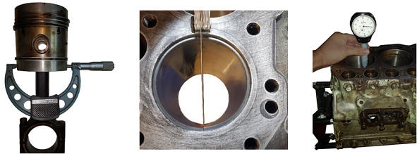
The wear of the cylinder liners is measured with a suitable measuring object. The indicator shows the degree of wear. The image shows the cylinder measurement of cylinder 4. Especially on the side where the crosshead force occurs, the cylinder diameter may have increased. The cylinder walls may show some wear, but it must be within tolerances. The measurement results showed that allowable wear was present on the cylinder walls. An optical inspection of the cylinder liners showed that some areas of the walls were smooth. The honing grooves were barely, if at all, present.
The honing grooves, a type of small scratches, ensure that there is always a small oil film between the piston ring and the cylinder wall. This oil film’s main task is lubrication, but it also serves as sealing and therefore helps achieve the final compression pressure. Using a designated honing stone, new honing grooves were applied to all four cylinder liners. The image shows this operation. Efforts were made to apply the honing grooves as crosswise as possible, at an angle of 45 degrees.
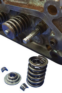
The valves seal the combustion chamber above the piston. Leakage along the valve seat results in compression loss; something that needs to be prevented. To check the condition of the valves and the valve seat, all valves must first be removed from the cylinder head. The image shows a disassembled valve spring of the intake valve of cylinder 1. The valve heads of the valves of cylinder 1 were so deteriorated that it was decided to replace both.
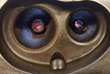
After disassembly, some valve seats appeared to be recessed/damaged. The image below shows the valve seats of cylinder 1. The engine likely would not have functioned properly if this check hadn’t been performed. Simply lapping the new valves would not be sufficient, so it was decided to machine the valve seats.
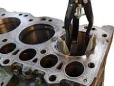
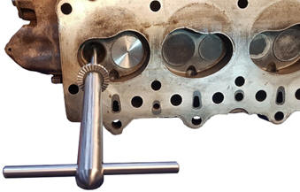
With a valve seat cutter, a small amount of material is removed to smooth the valve seat again. The cutter’s shaft is inserted into the valve guide (see image below). This ensures that the cutter can be positioned straight on the seat. During processing, two different angles were taken into account while machining. The valves of cylinders 1 and 2 were the most affected. For completeness, all eight valve seats were machined. After cutting, the valves were lapped with a special grinding compound to ensure the best possible seal.
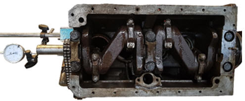
The axial crankshaft play of the crankshaft with three main bearings and two thrust bearings is measured with a dial gauge. If there is too much axial play and no mechanical defect is present, a thrust bearing of a larger size can be installed. The measurement seen in the image showed that the axial play was fine.
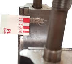
The clearance between the plain bearings of the crankshaft and connecting rod, in other words, the radial crankshaft play, is measured with Plastigage (see image). Plastigage is a special synthetic thread that deforms permanently after compression. After mounting the bearing cap or connecting rod, the Plastigage leaves an imprint. The width of the imprint indicates how much clearance exists between the plain bearing and the crankshaft.
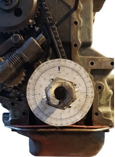
The timing chain transfers the movement of the crankshaft to the camshaft. After installing the pistons, crankshaft, and cylinder head, the timing chain needs to be adjusted again after fastening. Due to the absence of adjustment and marking points, the adjustment had to be determined based on the asymmetrical valve timing diagram. Using a degree wheel on the crankshaft, it can be determined at what angle the intake and exhaust valves open and close (see image). The timing components such as gears, chain, guide, and tensioner were checked for optical wear. They were in good order.
All parts are tightened according to the prescribed torque. Since the engine is disassembled, checks must be carried out after a few kilometers driven. However, this is not possible because the engine is not being installed in a vehicle. Therefore, it is decided to follow the controls prescribed by Land Rover after 24 operating hours.
Mounting the engine on a mobile frame:
The goal was to use the engine as an educational tool, where it runs on an engine management system. The engine is not placed in a car. To ensure a safe and reliable setup, it was decided to mount the engine on a suitable engine frame. The intention is for the engine to be fixed on the engine frame at the original locations of the engine mounts. Since there are no ready-to-use conversion kits, the mounts had to be custom-made.
During the assembly phase, a decision had to be made on how the engine should be assembled. The tuning of the engine management system must be carried out under increased engine load. Because a transmission brake is present on the original transmission, it was decided to also mount the transmission on the engine frame. By operating this transmission brake, it is possible to temporarily load the engine during operation.
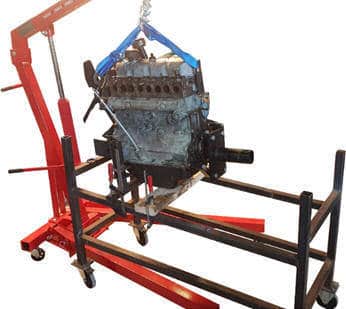
Working and modifying the existing engine mounts made it possible to connect the engine reliably with the frame. The engine frame also provides the opportunity to attach a dashboard, where, among other things, the controls can be realized. The image shows the moment when the engine is suspended above the frame and ready to be fixed.
The engine mounts on the distribution side are made from steel pipes and U-profiles. A motor rubber provides the damping. At the bottom, two pipes are mounted on top of each other to mount the combination of the engine block and transmission as horizontally as possible on the frame. Using M8 and M12 threaded rods, bolts, and nuts, the mounts are fixed to the engine block and the frame.
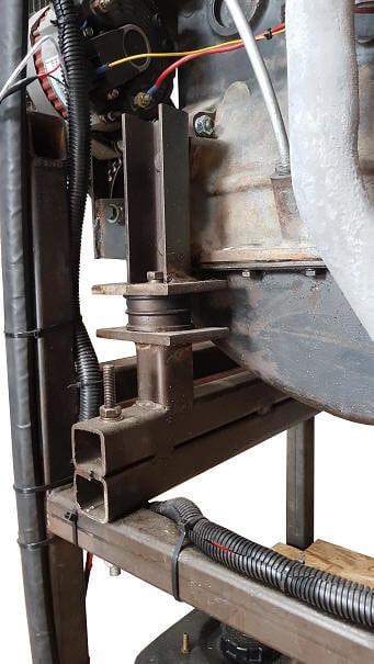
On both sides of the transmission, such a transmission mount is made that allows it to rest on the frame.
After the engine and transmission were safely and reliably mounted on the frame, the engine assembly could be resumed. After mounting adjustable and adjustable components, such as the carburetor and ignition, these were adjusted to factory values.
Other components are also mounted on the frame that makes the engine’s operation possible, such as the radiator, the dashboard with control options, and the fuel tank. These components are described in the following sections.
Cooling:
In its original state, the cooling is achieved by a large radiator and a metal cooling fan mounted on the water pump. Since the engine is not installed in a vehicle but on a mobile frame, it is important to use suitable aftermarket components. The metal cooling fan was replaced with an electrically driven cooling fan with plastic blades. Not only is the plastic version much safer as the engine is made suitable for educational purposes (consider personal safety when performing measurements) but it is also more suitable for faster heating of the radiator and engine block. The electric cooling fan can be switched on and off with a button on the dashboard. This allows the engine to warm up quickly, as there is little possibility to load it mechanically. In a warmed-up engine, there is earlier a “closed loop” where the data from the oxygen sensor is used to regulate fuel injection. In a cold engine – in “open loop” – extra enrichment occurs: when injecting a larger amount of fuel (λ < 1), the fuel correction by the oxygen sensor is undesirable.
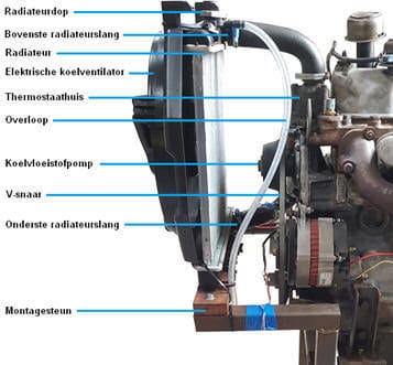
The image shows an overview of the components of the installed cooling system. The original radiator was not present. Because its size and weight were unsuitable for mounting on the engine frame, a smaller aftermarket radiator was chosen. The diameters of the connections of the upper and lower radiator hoses match the originals.
The upper and lower radiator hoses are custom-made with silicone hoses and couplers. The electric cooling fan is fixed on a mounting bracket. The upper radiator hose protects the radiator from tilting. With a pressure cap (0.9 bar), the cooling system is protected against excessive pressures. When the pressure rises too high, the valve in the radiator cap opens against the force and coolant flows through the overflow to a catch tank.
Through experimentation, it had to be determined whether the radiator had a sufficiently high flow capacity and whether the cooling fan had sufficient capacity to dissipate the heat. During the first test phase, the system was found to be in order.
Dashboard and electrical installation:
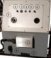
A dashboard is mounted on the frame, containing control lights, switches, the MegaSquirt ECU, various relays, and wiring bundles. The dashboard is used to control and monitor engine functions.
The image shows the dashboard. Number 1 in the figure indicates the location of the ground switch; a key breaks the connection to the battery ground. Since it is unnecessary to supply power to the shut-off engine, it is safer to interrupt the ground when the engine is left unattended. Number 2 indicates the switch for the cooling fan. Numbers 3 and 4 are the control lights for the alternator (D+), number 5 is the start button, and number 6 is the ignition switch (terminal 15). At the back of the dashboard is a fuse box. The MegaSquirt is mounted on the lower panel and is indicated by number 7. Number 8 indicates the fuel pump relay. The dashboard also offers the possibility to mount a breakout box on which students can perform measurements. This makes it possible to measure the sensor values and actuator control signals with the oscilloscope.
The original starter relay controls the starter motor; with a small start button, pin 86 is grounded, causing a control current to flow. The control current generates a magnetic field, causing a main current to flow between terminal 30 and 87; the starter motor is supplied with this main current until the start button is released.
The retrofitted alternator provides the charging voltage and charging current to the battery. A control light indicates whether the alternator is charging properly. The oxygen sensor, injectors, and coil receive a supply voltage from the fuse box. Other signal and ground wires provide information transfer and on/off commands from the MegaSquirt.
Fuel pump and tank.
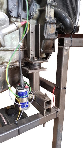
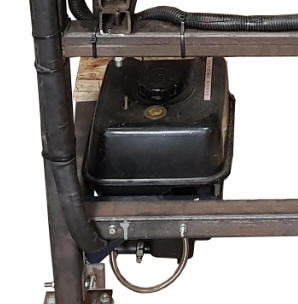
The mechanical fuel pump in the classic setup is no longer used when installing the components of the engine management system, as the working pressure is too low (200mbar). The required fuel pressure for MPI injectors controlled by the MegaSquirt ECU is 3 bar. A standard electronic fuel pump from a passenger car is sufficient. Due to limited space, a compact unit was chosen, where the fuel tank, pump, and filter are housed in one casing. A metal frame allows the unit to be mounted on the engine frame. At a later stage of the project, the fuel lines that form the connection between the fuel pump and the injectors in the intake manifold will be installed.
The power wires of the fuel pump run through a cable duct to the instrument panel, which has already been described. The positive wire of the pump is activated via a relay by the MegaSquirt.
Operating the engine in a classic setup.
Before installing the components for the engine management system, the engine was initially made functional in the classic setup, meaning with carburetor and distributor ignition. Chapter 5.2 describes the activities carried out to mount the engine and auxiliary components on the engine frame. In the first test phase, where the engine was started in the classic setup, checks could be made during the following conditions:
- Cold start;
- Idling;
- Increased speed, increased load;
- Running at operating temperature for an extended period.
During the above checks, it appeared that some repairs still needed to be made before the engine was reliable enough for conversion.
- After the first engine start, it appeared that the seal in the coolant pump was no longer in order; the coolant leaked past the bearing out of the engine block. Replacing the coolant pump was sufficient to solve the problem.
- The next issue was stalling when the engine reached operating temperature. The ignition failed, causing the engine not to restart. The problem was in the distributor and could easily be solved.
- Over time, an oil leak formed between the engine and the transmission. The leak is likely from the crankshaft seal. This leak will be fixed after completing the project.
Once the engine was found to be in good order in the classic setup, the electronics could be continued.
Next: Sensors.