Topics:
- Indirect and direct injection
- Fuel pressure regulation in indirect injection
- Injection strategy multi-point injection
- Electromagnetic injector (MPI)
- Piezo injector (DI)
- Injection strategies direct injection
- Dual injection
- Voltage and current measurement on a multipoint injector
- Injection timing relative to the crankshaft position
- Current limitation in the ECU
- Determination of the required amount of fuel
- VE table
- AFR table
Indirect and direct injection:
The types of injection systems in a gasoline engine are divided into indirect injection for the throttle, indirect injection per cylinder, and direct high-pressure injection. The following paragraphs on this page explain these different injection systems.
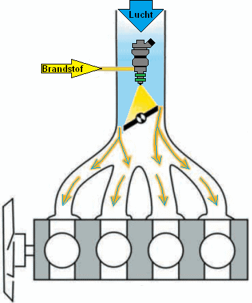
Indirect injection:
Before the throttle, there is an injector. The fuel is sprayed against the throttle, mixing with the flowing air. The major drawback is that there is no precise fuel dosing per cylinder; one cylinder always receives slightly more or less than another. Therefore, the system is not adjustable and is no longer used due to environmental requirements. This system is also known as central injection (Monopoint).
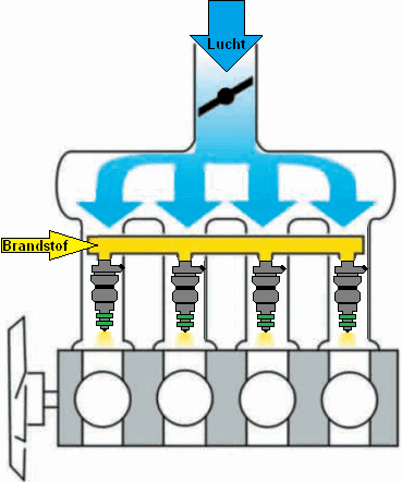
Indirect injection:
Each cylinder has its own injector. The injector sprays fuel onto the intake valve. The flowing air also mixes the fuel with the air before the mixture enters the combustion chamber. The advantage over indirect injection is that the amount of fuel can be more precisely controlled. This system is also known as MPI (MultiPoint Injection) or PFI (Port Fuel Injection).
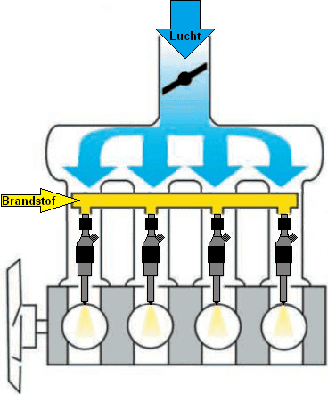
Direct injection:
The injectors in DI (Direct Injection) or DISI (Direct Injection Spark Ignition) are placed next to the spark plug at the top of the combustion chamber. The fuel is injected by this injector with high pressure of about 200 bar during the intake stroke. The major benefits of this system are that the fuel quantity can be controlled even more precisely, multiple injections can occur during the intake stroke, and the air-fuel mixture is cooler. This has enabled manufacturers to increase the engine’s compression ratio. The injector can be executed as a Piezo or solenoid injector.
For DI, higher injection pressures are needed than for MPI / PFI because the injection takes place during the compression stroke; the fuel must be sufficiently atomized while the air in the cylinder is compressed. Therefore, a separate high-pressure pump is present for DI. The high-pressure pump builds up fuel pressure in the fuel rail. The injectors are connected to this fuel rail with lines. As soon as the engine management sends a signal to the injector, it will open and close at the desired time.
The advantages of DI compared to PFI include:
- More precise injection;
- Multiple injections possible;
- Injection timing can be adjusted;
- Higher effective pressure above the piston possible (thereby making downsizing with a higher compression ratio possible);
- Lower fuel consumption, lower CO2 emissions.
The disadvantages include:
- Higher system costs due to a high-pressure fuel pump, advanced injectors, more complex cylinder head;
- Increased soot emissions (PM emissions);
- Direct injection into the combustion chamber provides cooling instead of the necessary heat for fuel evaporation.
An engine with dual injection uses the advantages of both systems. Direct and indirect injection can interchange based on operating conditions. The operation and application of dual injection is described in the similarly named paragraph on this page.
Fuel pressure regulation in indirect injection:
A constant fuel pressure is a prerequisite for accurately regulating fuel injection. At the top of the injector is the fuel pressure (rail pressure) and at the bottom is the intake manifold pressure. The pressure in the intake manifold varies with changing engine load and, without a pressure regulator, would influence the fuel pressure difference and thus the injection quantity. For this reason, a fuel pressure regulator is used. In this paragraph, we delve into the operation and purpose of this regulator.
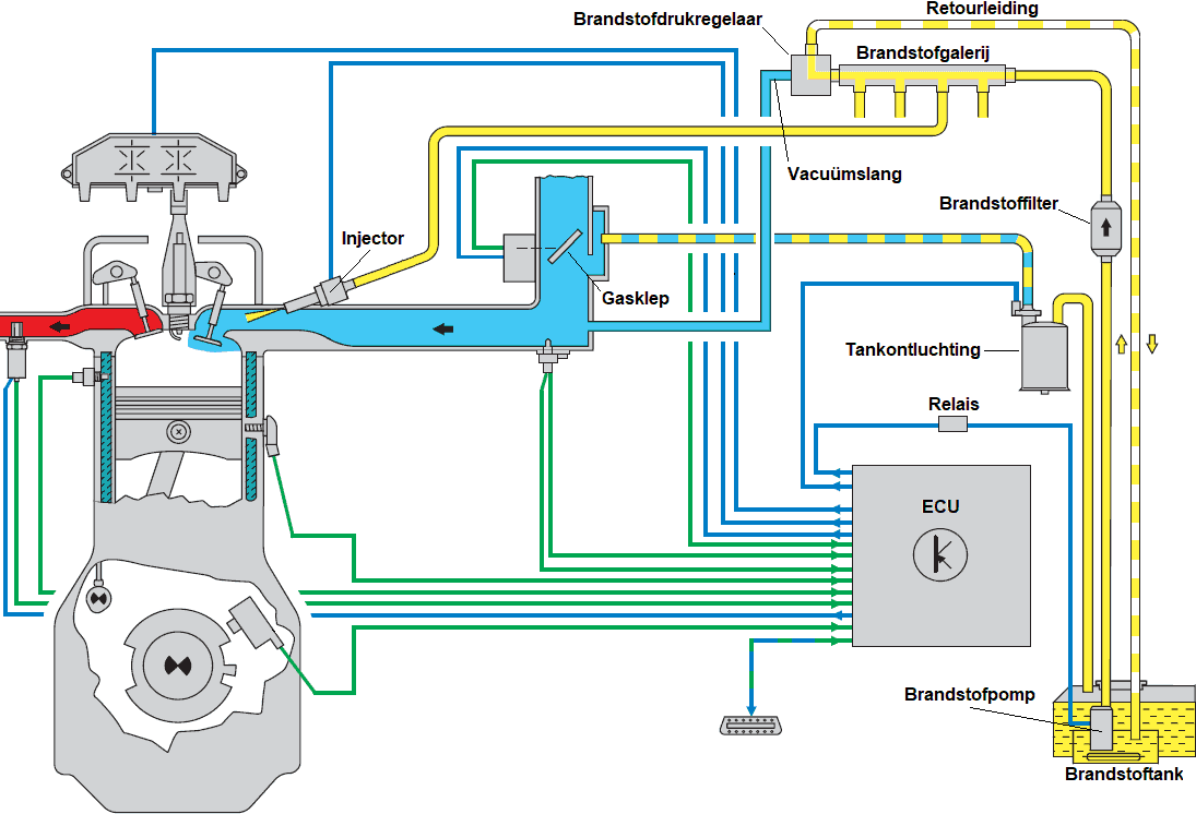
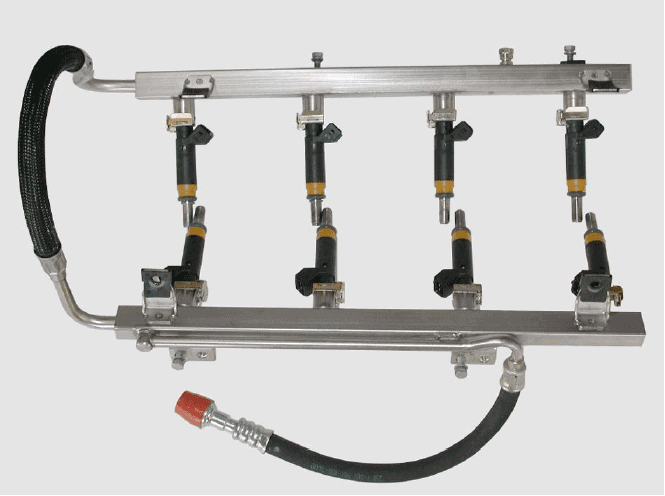
The image below shows the components of an indirectly injected gasoline engine with multi-point injection. We look at the fuel flow from the pump in the tank to the injector.
When the ECU activates the fuel pump relay, the pump starts. The pump draws fuel from the lowest possible part of the tank and pushes the fuel flow towards the fuel filter. Dirt particles in the fuel remain in the filter material. The filtered fuel then reaches the fuel rail. In most cases, the fuel rail is directly mounted on the injector entrance.
In the fuel rail, there is constant pressure: only upon electrical control of the injector by the ECU (see the blue wire) does the injector open, and the fuel is injected into the intake manifold onto the open intake valve. The amount of injected fuel depends on:
- the injection time (determined by the ECU by lengthening or shortening the injection signal);
- the fuel pressure (at an injection time of 2 milliseconds, the injector sprays more at higher fuel pressure than the ECU calculated).
The fuel pressure in the fuel rail (also called rail pressure) is adjusted based on engine load. We will delve deeper into this in the next paragraph.
Without using a pressure regulator, the following situations arise:
- At idle speed, the higher vacuum (thus a low air pressure) in the intake manifold would result in an undesirably higher gasoline pressure;
- During acceleration, there is less, or even hardly any vacuum (full load), and the gasoline pressure would drop, while a higher gasoline pressure is desired at that time.
With the fuel pressure regulator, the gasoline pressure in the fuel rail is increased or decreased based on the air pressure in the intake manifold. The fuel pressure regulator can be considered a dynamic valve, which allows an opening between the supply line from the fuel pump and the return line.
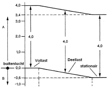
On the right, we see a fuel pressure diagram where the relative pressure difference in all circumstances (idle, part load, and full load) is 4 bar, thanks to the pressure regulator.
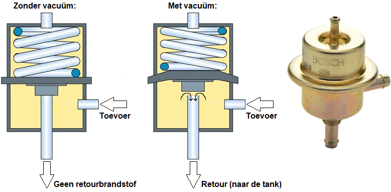
The explanation below pertains to the images where the pressure regulator is visible in the situation without and with vacuum. On the right is a Bosch fuel pressure regulator, used by multiple automakers.
Without vacuum (left):
The pressure regulator is closed at rest: the spring presses the diaphragm shut, preventing the supplied fuel from reaching the return line.
With vacuum (middle):
When the pressure above the diaphragm is reduced, the fuel pressure on the supply side pushes the diaphragm upward against the spring force. An opening is created, allowing the supplied fuel to be diverted through the return line to the fuel tank.
Injection strategy multi-point injection:
In (indirect) multi-point injection, three different injection methods are applied:
- Simultaneous: injection occurs simultaneously in all cylinders.
- Grouped: injection takes place per group; there is a distinction between one or more groups.
- Sequential: each injector is individually controlled and has its own injection moment.
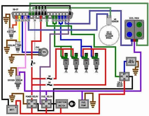
The engine management system in the image below illustrates grouped injection. The injectors of cylinders 1 and 2 share a common power supply (red) and are both switched to ground (green) simultaneously. The injectors of cylinders 3 and 4 are controlled similarly, but separately from cylinders 1 and 2.
Electromagnetic injector (MPI):
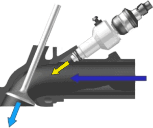
The electromagnetic injector is used in many gasoline engines that do not use (direct) high-pressure injection with a separate high-pressure pump. The fuel is under a constant pressure of 1 bar at the injector’s input. The fuel pressure is provided by the fuel pump in the tank. In multi-point injection (this will be described later on the page), each cylinder has its own injector. This injector is mounted in the intake manifold and injects fuel before the valve opens, with a maximum pressure of 6 bar. The fuel then has enough time to mix with all the oxygen (indicated as the dark blue arrow in the image) that flows into the cylinder as the intake valve begins to open.
The engine control unit monitors the crankshaft position to regulate the injection and ignition timing. Based on multiple factors (engine and ambient temperature, load, rpm, etc.), it will send a signal to the injector to open at the right moment. The connector of this injector has two wires. One wire has a constant positive voltage of around 14 volts. The other wire is grounded by the ECU to allow current to flow through the injector coil. Once the coil is sufficiently charged, the injector needle opens against the spring force. When the control stops, a spring pushes the injector needle back. This cuts off the fuel supply. When the control stops, the coil is still electrically charged. The energy in the coil forms an inductive spike, which can be observed on the oscilloscope. The inductive voltage briefly reaches around 60 volts.
These injectors are supplied with fuel by the fuel rail (also known as the fuel gallery). The lift pump in the fuel tank provides the pressure in the fuel rail. The fuel pressure in the rail is constant (approximately 4 bar). Because the pressure is so low, the injectors are secured with a locking clip and an O-ring for sealing. Especially in older cars where the system is disassembled, it is advisable to replace the O-rings before installation.
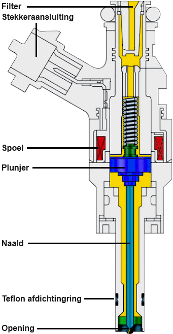
The housing of an injector is usually made of plastic. At the top of the housing, there is a plug connection that is internally connected to the coil. At the top, there is a rubber O-ring over which the fuel gallery is slid. At the bottom, there can be O-rings or Teflon sealing rings. An O-ring is mainly used in MPI injectors with low-pressure injection, while Teflon rings are used in engines with high-pressure injection, such as an FSI engine.
The coil is wrapped around the core of the injector. In the attached image, the coil is marked in red. In the middle of the injector, also internally in the coil, there is a plunger. This plunger has a mechanical coupling with the needle. Above the plunger is a spring that keeps the plunger and thereby the needle seated, closing the spray opening.
When at rest, the voltage at both coil connections is approximately 14 volts relative to ground. To make the injector spray, the engine ECU supplies one side of the coil with ground, while the other side receives positive voltage. At that moment, current begins to flow through the coil, resulting in the formation of a magnetic field. This magnetic field pulls the plunger and, thus, the injection needle upwards.
When the injection needs to be terminated, the ECU interrupts the ground, causing the magnetic field to disappear. The spring pushes the plunger back down, closing the needle and stopping the fuel flow to the combustion chamber.
The injector typically has several openings. These openings are very small, causing the fuel to be injected as a mist from the injector into the combustion chamber. The finer the mist, the easier it evaporates.
Piezo injector (DI):
Piezo injectors can be used in both gasoline and diesel engines. BMW was the first brand to apply piezo technology in gasoline engines, but they have stopped doing so in newer engines.
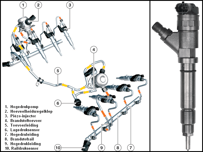
A piezo injector is a component of high-pressure injection. A separate high-pressure pump provides pressure on the fuel rail. This fuel rail distributes fuel to all injectors (see image). Due to the very high pressures, aluminum lines with fittings are used. The fittings (screwed onto the line and the injectors) must always be tightened with the correct force. This is stated in the repair manual of the respective engine.
The piezo element in the injector has the property of changing length when a positive or negative voltage is applied. This property is utilized in the injector. Once the engine control unit delivers a control voltage of about 100 to 150 volts, the piezo element expands by approximately 0.03 mm. This length change is enough to create a connection between the high and low-pressure chambers, starting the injection immediately. The piezo element can switch on and off within a thousandth of a second. Along with the very high injection pressure of up to 2000 bar, this results in very fast and accurate injections. Additionally, multiple injections can occur in quick succession at these speeds.
Multiple injections during the intake stroke have the advantage of optimizing the air-fuel mixture. The high pressure causes the fuel droplets to be ultra-finely atomized, allowing for better mixing with the air. Up to eight injections can occur during the intake stroke, positively affecting fuel consumption, power, and exhaust gas emissions.
Injection strategies direct injection:
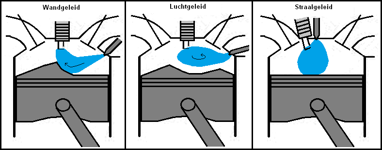
The injection strategy of direct injection has different variants: wall-guided, air-guided, and spray-guided (see the images below). These scenarios involve a stratified combustion process. This is not applicable in all operating conditions.
- Wall-guided: The piston guides the fuel cloud to the spark plug. The distance between the spark plug and injector is large. Applied in GDI and HPI engines.
- Air-guided: The air movement brings the fuel cloud to the spark plug. The distance between the spark plug and injector is large. Applied in FSI and JTS engines.
- Spray-guided: The spark plug is at the edge of the fuel cloud. The distance between the injector and the spark plug is small. Applied in BMW engines.
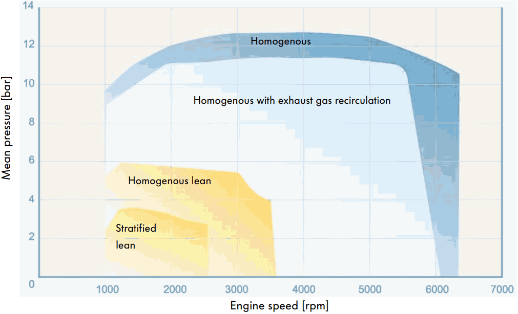
As previously indicated, stratified combustion is not present in all operating conditions of direct-injected gasoline engines. Engines with spray-guided direct injection can run stratified at part load. A stratified combustion process means that different air layers are present in the combustion chamber. Near the spark plug, the lambda value is 1. Further away, the lambda value increases (leaner, so more air). This air creates an insulating air layer. In a stratified process, the injection timing is later than in a homogeneous process. Stratified injection allows the throttle to be fully opened, reducing the choking effect on the air. With less resistance, the drawn-in air is less restricted, making it easier to be drawn in. As the lambda value in the combustion chamber is still less than 1 during stratified injection due to the insulating air layer, there are no combustion issues. During the stratified process, fuel consumption decreases.
With a homogeneous mixture, the lambda value is 1 everywhere. For a gasoline engine, this means the air to fuel ratio is 14.7:1 (14.7 kg of air to 1 kg of fuel). Any engine can run homogeneous. If enriched, the lambda value drops, and if the mixture is made leaner, the lambda value rises:
<1 = Rich
>1 = Lean
An engine will always oscillate between lean and rich to keep the catalytic converter working efficiently. The lambda sensor sends the data to the engine management system.
At full load, the engine always runs homogeneous. This provides higher torque than in a stratified process. When the engine runs homogeneous, fuel is injected early. Also, when starting from a standstill, the engine runs homogeneous. There is higher starting torque than if the engine were running stratified.
The characteristic below shows the operating situations at different speeds relative to the combustion pressure, with and without the use of EGR.
Dual injection:
The VAG group uses gasoline engines with dual injection to meet current emission standards. In engines with dual injection, there are two fuel injection systems: a low-pressure and a high-pressure system. a0
- The low-pressure system includes MPI injectors that have been used for decades. The MPI injectors are located in the intake manifold and inject into the intake valve at a pressure of 4 to 5 bar;
- The high-pressure system includes high-pressure injectors that inject directly into the combustion chamber with an injection pressure of up to 150 to 200 bar.
The engine management system determines which injector is controlled. a0
The following image shows a cross-section of the cylinder head with the two fuel systems.
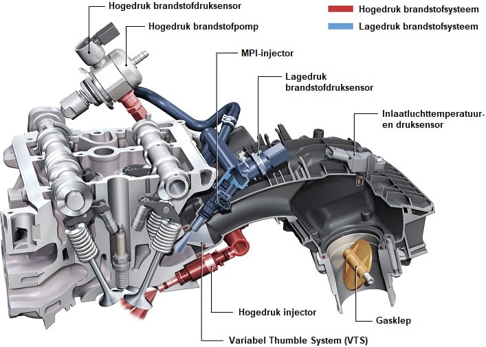
The MPI injection offers better mixing between air and fuel. The direct injectors are used at idle speed and full load. In direct injection, better cooling is achieved, allowing for a higher compression ratio. However, the mixing of air and fuel is not optimal. This results in more soot emissions. Engines with direct injection are now often equipped with a particulate filter because of this. This is not an issue with dual injection. The “Variable Tumble System”, abbreviated VTS, is a version of a variable intake manifold that improves airflow through better passage. The “tumble” is an air movement that is swirled when entering the cylinder. The air swirl is needed to properly mix the fuel from the MPI injector with the air.
The dual injection in combination with VTS ensures better exhaust emissions. An added advantage is that the intake valve is cleaned by the MPI injector. Engines with direct injection often suffer from a clogged intake path (intake manifold and intake valves), leading to necessary problems like restricted air supply. In extreme scenarios, the intake becomes so clogged that the intake valve cannot properly seal against the cylinder head, eventually burning out due to insufficient heat dissipation.
It is known that VAG engines with dual injection in Europe come with direct injection only in the United States, with the intake manifold sealed off. This is because, at the time of writing, emission standards in Europe are stricter than in the USA, and cost considerations lead the manufacturer not to equip engines with such costly systems in markets where emission standards are less stringent.
Voltage and current measurement on a multipoint injector:
The oscilloscope can only measure voltage. Measurement cables can be connected in parallel over the electrical components. Measuring current in series is not possible. Using an inductive current clamp, the current can be measured. The Hall sensors in the current clamp measure the magnetic field and convert it into a voltage. The voltage can be measured with the oscilloscope. In this case, there is a conversion factor of 10 mV per ampere; for every 0.010 volts that the current clamp transmits, this can be converted to 1 A.
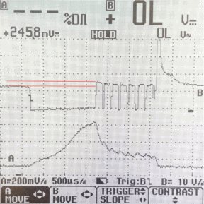
The following oscilloscope image shows the voltage and current profile of an electromagnetic injector.
- Red: voltage profile;
- Yellow: current profile.
At rest, the voltage is 14 volts. There is no voltage difference on the connector, so no current flows. The ECU switches one wire to ground to control the injector. Due to the voltage difference, current flows through the injector coil.
The yellow line indicates the current profile: as the voltage drops to 0 volts, the current buildup begins. Charging the coil takes time. The current does not rise above approximately 0.9 A. Halfway through the current buildup, there is a kink in the line: this is the moment when enough magnetism is built up to lift the needle off its seat. The injector begins to inject.
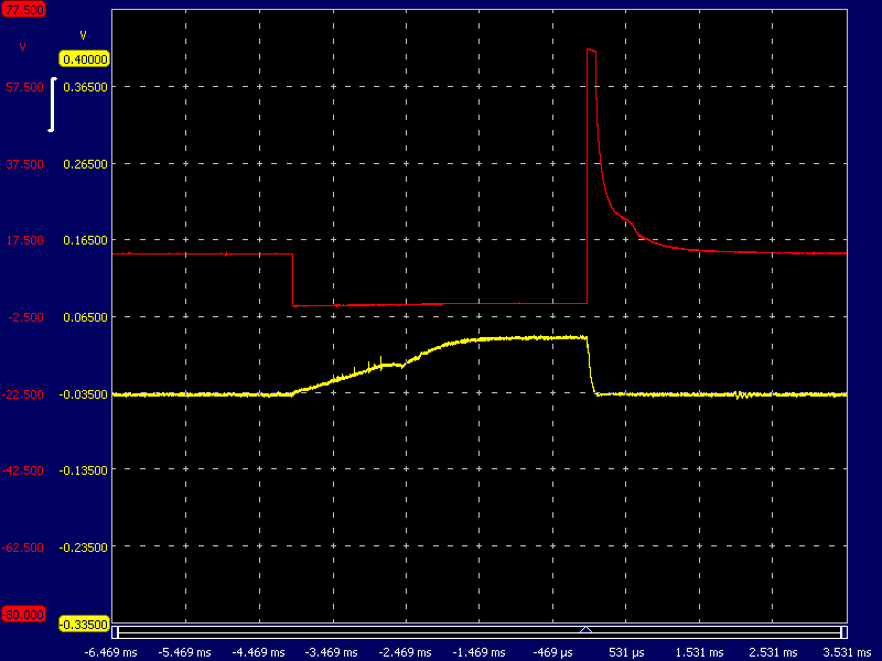
The ECU interrupts the ground connection to stop the control. The residual energy in the coil causes an inductive voltage of approximately 60 volts. The injector stops injecting as the spring presses the needle back onto its seat. This is visible in the oscilloscope image as a bump in the voltage signal.
If the engine is running irregularly and there is evidence of cylinder misfire, this can be due to several causes:
- No or poor spark due to a faulty spark plug, spark plug wire, or coil;
- Restriction in the fuel supply due to a clogged fuel filter, faulty pressure regulator, problem with the fuel pump, or injector;
- Compression loss due to issues with the piston rings, faulty head gasket, or valve seals.
During diagnosis, a scope can be used to check if the injectors are still functioning correctly. At the beginning of this paragraph, measurements are shown where there was no malfunction. With the help of blue lines, as an example, indications are given of what the voltage and current profile of a faulty injector would look like.
If the injector control is correct but no kinks are visible in the voltage and current image, it can be concluded that the injector needle is not moving. Because the injector for one cylinder is not working properly while the other injectors are functioning correctly, the images of different injectors can be easily compared. If handled carefully, a tap on the injector can cause the needle to dislodge. In that case, the engine immediately runs smoother, and the kinks become visible again in the scope images. However, this does not guarantee a permanent solution; the problem is likely to return shortly. Replacing the respective injector is necessary.
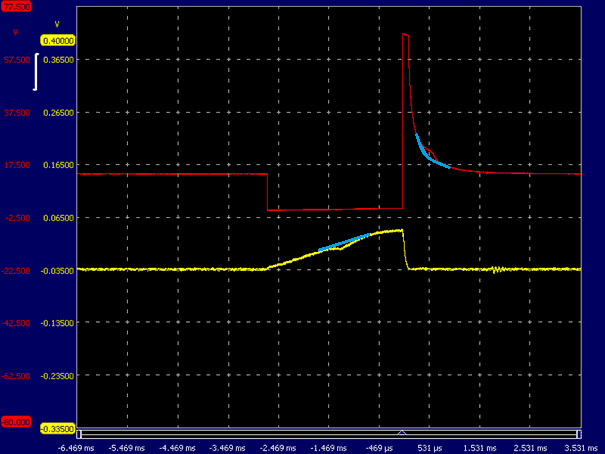
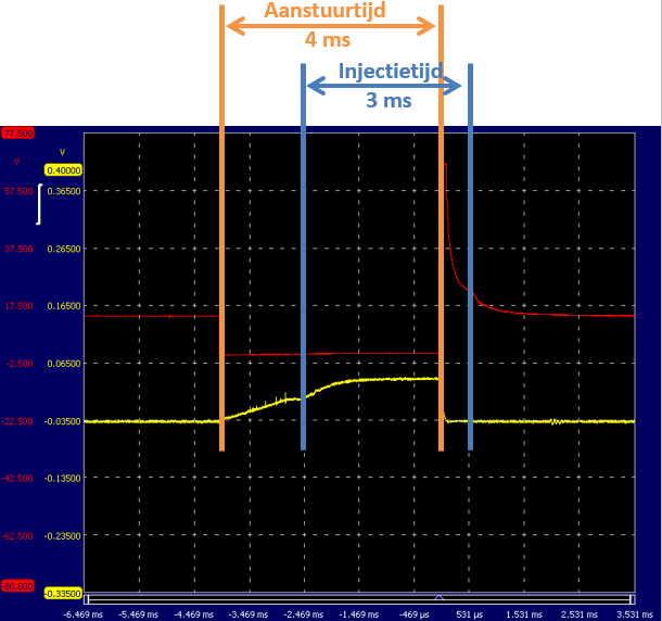
The needle in the injector opens only after the coil is sufficiently charged. Thus, the injector does not immediately inject fuel when the ECU starts the control. After ceasing control, the spring presses the injector needle onto its seat. This also takes time. The control time is usually not equal to the injection time. The following image shows the voltage and current profile of the same injector as above, but with increased speed.
- Start of control: the ECU switches the control wire to ground. Current flows through the injector coil to open it. The kink in the current profile indicates the moment when the injector needle opens. Subsequently, the current rises a bit more and remains constant. The injector needle stays open.
- End of control: as previously described, in the voltage profile, the moment of injector needle closure is identified by a bump.
The control lasts 4 ms, but the actual injection time is 3 ms. The difference between these is called the “delay”. The ECU controls the injector for 4 ms to inject for 3 ms.
Injection timing relative to the crankshaft position:
With the help of an oscilloscope, the injection moment can be observed. Channel A (red) is connected to the injector’s ground wire, and Channel B (yellow) is connected to the wire of the crankshaft position sensor. While the engine is running, this oscilloscope image allows us to determine both the injection timing and the injection duration.
This oscilloscope image was taken at idle speed. The red voltage profile shows the opening and closing of the injector (see the paragraph: voltage and current measurement on a multipoint injector). At the time -2.860 ms, the control begins; the voltage drops from 12 volts to 0 volts. This is the point where the injector coil is grounded and current begins to flow. The injector’s control ends when the red line rises again. Due to the energy built up in the coil, an inductive voltage of more than 60 volts occurs. The voltage gradually drops to 12 volts afterward; here, the injector is turned off again.
The red AC voltage comes from the inductive crankshaft position sensor. Each time the teeth of the trigger wheel pass the crank sensor, a sinusoidal AC voltage is generated. The trigger wheel has 60 teeth, of which 2 are ground off. The two missing teeth form the reference point, where the engine management system recognizes that the pistons of cylinders 1 and 4 are between 90° and 120° before TDC (top dead center). After recognizing the missing tooth, the engine management system has time to determine (possibly in conjunction with the camshaft sensor) the correct injection and ignition moment and to control the injector and coil before the piston reaches TDC.
In the oscilloscope image, the timing of the start of injection is visible; at the fourth pulse of the crankshaft sensor, the injection starts. Assuming there are 60 – 2 teeth present, injection occurs every 6° rotation of the crankshaft (360° for one revolution / 60 teeth). Injection starts 24 degrees after the reference point. The missing tooth is located 90° before TDC, so the injection begins (90° – 24°) = 66° before TDC.
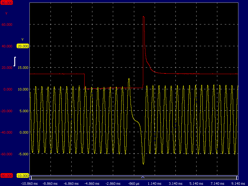
At an increased speed of 2000 rpm, the pulses of the inductive crankshaft sensor are closer together. The frequency of this signal is translated by the engine management system into a speed. Depending on the speed, load (measured by the MAP sensor), and the temperatures of the intake air and coolant, the required injection time is determined. The injection timing occurs earlier, and the injector remains grounded longer: the injector sprays earlier and longer.
From the start of the control to the trigger point (arrow at the turn-off point of the injector), the control lasts about 5.2 ms. The time the injector is controlled does not equal the actual injection (see the previous paragraph).
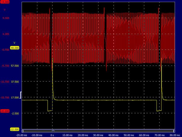
In the next oscilloscope image, the inductive crank signal is shown in red, and the injector signal is shown in yellow. By increasing the engine speed to around 3000 rpm, two injector controls are visible. It is clearly seen that fuel injection of cylinder 1 occurs with every second crankshaft rotation.
Current limitation in the ECU:
As indicated in the paragraph “Voltage and current measurement on a multipoint injector”, there is a delay between the control and the actual opening of the injector needle. In this case, it takes 1.5 ms to open.
The injector needle would open faster if the current through the coil increased faster. The current strength depends on the coil’s resistance: the lower the resistance, the faster the current builds up. The high-impedance injectors used in the test engine have a resistance of 16 Ohms. At a board voltage of 14 volts, a small current flows:
The current is sufficient to open the injector needle but not too high to become too warm due to the high power:
Since only a low power is developed, there is no need to use a current control system. This would be necessary for low-impedance injectors.
- Low-impedance injectors have the advantage that the current buildup increases rapidly from the beginning. This results in a quick opening of the injector needle, with little delay.
- Low-impedance injectors have a resistance of about 2.8 ohms. Due to the low resistance, a high current flows:
The power also increases significantly:
The absorbed power is almost seven times higher than that of high-impedance injectors. If the current rises too high, heat generation occurs in the injectors and the final stage of the control unit. To limit the current strength, the voltage is switched on and off several times in a short time. Once the injector needle is opened, it takes little energy to keep the needle open. During the on and off switching, the current strength decreases. This trend is visible in the oscilloscope image.
Determination of the required amount of fuel:
The required amount of fuel is determined by the manufacturer in various maps stored in the ECU’s ROM memory. The engine management system reads from these maps how much fuel is needed without corrections. This, of course, depends on engine speed, temperature, and load. The main maps used to determine the correct amount of fuel are explained in this paragraph as the VE table and AFR table.
VE table:
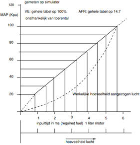
The VE table represents volumetric efficiency and the air/fuel ratio at every engine speed and intake manifold pressure. Volumetric efficiency is the ratio between the actual amount of air filling the cylinders and the amount of air the cylinder would fill in a static situation, depending on the speed and intake manifold pressure. The values in the table are used by the ECU to determine the actual air mass and, thus, the filling rate. With this data, the amount of fuel to be injected is calculated.
This theoretical approach deviates from reality. No account has yet been taken of the engine specifications. Consider the valve timing diagram (valve overlap, or possibly variable valve timing), air resistance in the intake path, etc. Therefore, a correction factor is applied that gives a deviation from the linear relationship. The correction factor is shown in the image above with a dashed line. The curve indicates how correct the linear relationship is. At a pressure of 60 kPa, the deviation is about 50% from the line representing the linear relationship. The correction factor can be expressed as a percentage.
In a VE table, each cell provides the percentage corresponding to the vacuum in relation to engine speed. This percentage will be highest at the engine speed where torque is highest. After all, the engine is most efficient because it fills the best.
The values in the VE and AFR tables later in this paragraph are derived from the torque and power curve of a 1.8 20v engine from a VW Golf.
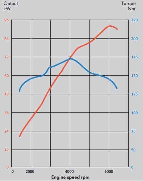
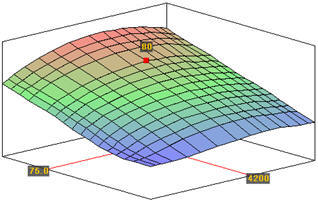
The images below show the VE table as an input table and the three-dimensional representation created based on the torque and power curve in the program “TunerStudio”. This program is mainly used to provide a programmable ECU such as the MegaSquirt or Speeduino with software. For more information, see the pages about the MegaSquirt project.
On the vertical axis, the MAP (Manifold Air Pressure) is shown from 15 kPa (high vacuum) to 100 kPa (atmospheric pressure). The MAP indicates the engine load. The horizontal axis shows the engine speed from idle to maximum engine speed.
The cells in the VE table show the engine’s filling efficiency. In other words; how efficient the engine is at a specific speed and load. Around the speed where torque is highest (about 4200 rpm), the engine is most efficient; the percentages are highest here. Here the engine fills the best. Applying techniques that increase filling efficiency, such as variable valve timing, intake manifold adjustment, or turbo application, benefits the percentages.
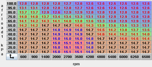
AFR table:
The required air/fuel mixture is recorded in an AFR table. AFR stands for “Air Fuel Ratio”. At a stoichiometric mixture (lambda = 1), 14.7 kg of air is needed to burn 1 kg of gasoline. A stoichiometric mixture is not desired in all situations.
- A lean mixture benefits fuel consumption;
- A rich mixture allows for higher power.
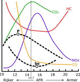
When the engine needs to deliver more power (P), enrichment occurs. Additionally, a richer mixture provides cooling. Enriching to λ = 0.8 means that a mixture ratio (AFR) of 11.76 kg of air to 1 kg of fuel applies. There is, therefore, less air available to burn 1 kg of fuel than with a stoichiometric mixture. On the other hand, a lean mixture provides more favorable fuel consumption (be) but increases the risk of knocking. Enriching or leaning the mixture must always remain within combustion limits.
During idle operation, the speed is between 600 and 900 rpm. The throttle is almost completely closed, and the vacuum is high: it is between 25 and 40 kPa. The mixture in this speed range is stoichiometric (14.7:1).
In the case of part load, the engine speed will have increased to 4200 rpm. The throttle is more open, so the vacuum in the intake manifold decreases to 40 – 75 kPa. With increasing engine load, the vacuum decreases, and enrichment occurs (AFR of 13:1). A lean mixture is possible at a low engine load. At full load, the throttle is fully open. The vacuum drops to 100 kPa (atmospheric pressure), and maximum enrichment occurs (12.5:1).
The lambda value not only affects power and fuel consumption but also exhaust gas emissions. A richer mixture results in lower NOx levels but also higher CO and HC emissions. In a leaner mixture, the fuel particles are further apart, leading to less optimal combustion; resulting in increased HC emissions.
When applying a catalytic converter, it is desirable to have the injection constantly alternating between rich and lean. A rich mixture forms CO as a result of an oxygen deficiency, which the catalytic converter uses to reduce NOx. A lean mixture contains an excess of oxygen, which oxidizes CO and HC.
The control unit determines how much fuel should be injected. First, the basic injection data is read from the maps. The values from the VE and AFR tables help calculate the injection amount. The following values set by the manufacturer are also considered:
- Enrichment depending on coolant and intake air temperature;
- Short-term acceleration enrichment when the throttle is opened quickly;
- Correction due to variations in the board voltage.
In addition to these set values, the ECU continuously considers the voltages sent by the lambda sensor. These voltages depend on the oxygen content in the exhaust gases, which is a continuously changing variable. The input from these sensor voltages is processed as so-called “fuel trims“.
How the values of the VE and AFR tables and the other mentioned settings are determined is described on the pages of the conducted MegaSquirt project.