Subjects:
- Preface
- Positioning of the sensor and pulse wheel
- The missing tooth in the pulse wheel
- Operation of the crankshaft position sensor
- Measuring signals with the oscilloscope
Preface:
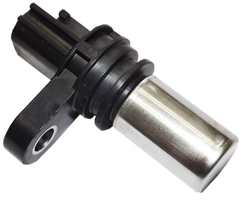
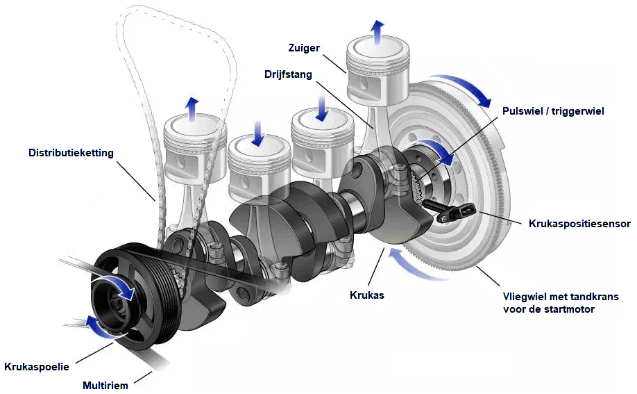
The crankshaft position sensor (also called the TDC sensor or engine speed sensor) is usually mounted on the bottom of the engine block at the height of the flywheel. When the engine is running, the crankshaft position sensor reads the cogs or magnets of the pulse wheel moving past the sensor's sensing element. The crankshaft position sensor gives a change in the magnetic field between the sensor and the pulse wheel change in the signal voltage (inductive or Hall). The speed at which these pulses follow each other is an indication of the speed. At some point, one or two missing teeth are missing from the pulse wheel. The signal that follows from this is for the motor engine control unit an indication of the position in which the pistons are located. With this, the engine management determines, among other things, the injection time and the ignition time. The crankshaft speed is also sent to the tachometer sent in the instrument cluster.
Positioning the sensor and pulse wheel:
The pulse wheel (also called the trigger wheel, reference wheel, or reluctor wheel) can be located in or on the motor in several places:
- externally on the crankshaft pulley: in older engines we see that the crankshaft pulley, through which the V-belt or multi-belt is driven, has teeth. We no longer encounter this form of external pulse wheels in modern engines;
- internally by means of ground teeth on the crankshaft: the pulse wheel is located on the crankshaft on the inside of the crankshaft flange and can be seen when the sump pan has been removed;
- externally at the level of the rear crankshaft seal: on the outside of the engine block, between the outside of the crankshaft flange and the flywheel, a toothed ring or magnet ring is fitted. This is accessible when the flywheel is removed.
The crankshaft sensor faces the pulse wheel. In modern engines, the crankshaft sensor is usually located on the side of the engine near the flywheel. The illustrations below show three different installation locations of the crankshaft position sensor and pulse wheel: teeth on the crankshaft on the inside of the flange, and on the outside of the flange a magnet ring and toothed ring.
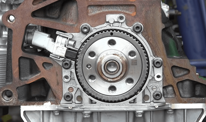
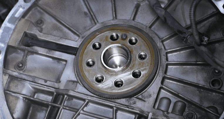
The images above show pulse wheels with crankshaft position sensors used at VAG and BMW. The version that is often used at VAG consists of a cassette in which the toothed pulse wheel also contains the housing of the crankshaft seal. The magnet ring from BMW has been slid over the crankshaft flange. When replacing the flywheel, care must be taken that this magnetic ring does not fall out. It is more common that after replacing the clutch including flywheel, the engine no longer wants to start, because the magnetic ring has not been mounted back.
The missing tooth in the pulse wheel:
The crankshaft position sensor measures the teeth on the reference wheel, which is mounted on the crankshaft. The crankshaft position sensor “counts” the teeth that pass and “notes” that a tooth is missing in every revolution. Based on this missing tooth, the engine management system knows in which position the crankshaft is, and therefore also at what height the piston is in the cylinder during the compression stroke.
The missing tooth is located at the point where the piston of cylinder 1 is between 90 and 120 degrees before TDC. The name “TDC sensor” is therefore incorrect: the sensor does not measure the point when the piston is at TDC, but the position in which the piston is to move to TDC.
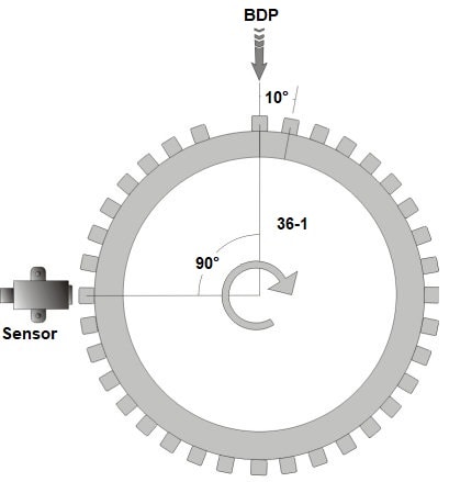
Many motors are equipped with a 36-1 or a 60-2 pulse wheel. In this example we will cover the 36-1 pulse wheel. This pulse wheel has 36 teeth, one of which has been ground away. So every crankshaft rotation (360°) passes 36 (minus the missing) teeth. This means that every 10° one tooth passes the sensor.
In the image we see that the missing tooth is almost at the top. In this position the engine is at TDC. The direction of rotation is clockwise, so 90° earlier the missing tooth was rotated past the sensor. This position is the reference point. In this 90° rotation, the piston of cylinder 1 has moved from ODP to TDC.
The moment the missing tooth passed the sensor, the sensor translated this into a change in the crankshaft signal, and this was the recognition point (reference point) for the engine management system to start injecting and/or igniting a few teeth later.
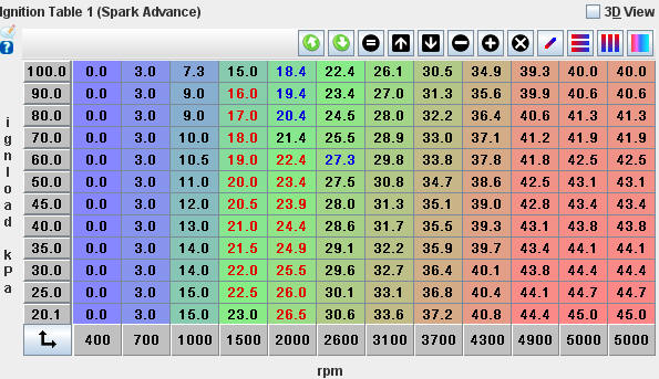
An increase in engine speed or engine load is referred to as “pre-injection" or "ignition advance“. This is possible using the reference point at 90 or 120° before TDC. Example regarding the ignition timing:
- At low speed and low load (1000 rpm at 25 kPa) the ignition advance is 15°† This corresponds to one and a half teeth before TDC;
- At increased speed and increased load (3100 rpm at 60 kPa) the ignition advance is almost 30°† This corresponds to three teeth before TDC.
When, in the latter situation, three teeth before TDC have to be ignited, the engine management system has time to ignite the ignition coil between 9 teeth (90°) from the reference point and three teeth (30°) from the desired ignition time. so that ignition is initiated before the piston reaches TDC.
A crankshaft position sensor sends a signal from which the engine management system can deduce that the piston of cylinder 1 is in position 90° of 120° before TDC. What is not known is whether the piston is engaged in the compression stroke or the exhaust stroke.
- An engine with only a crankshaft position sensor is fitted with a DIS ignition coil, in which all spark plugs spark every crankshaft rotation, so that there is a “wasted spark” during the exhaust stroke;
- A camshaft sensor is required for individual control of pin ignition coils and injectors. From the information from the camshaft sensor, the engine management system can determine that cylinder 1 is engaged in the compression stroke, and not the exhaust stroke.
With the combination of the crankshaft and camshaft sensor, the speed and the control of the injection and ignition system are realized per cylinder.
Operation of the crankshaft position sensor:
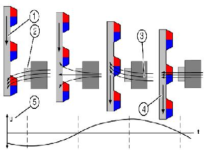
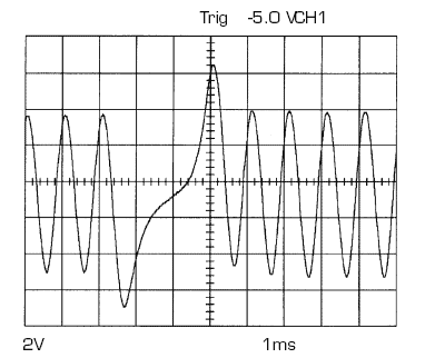
The lower left image shows the magnetic field lines created when a crankshaft tooth moves past the magnet of the crankshaft position sensor. The crankshaft signal can be seen in the lower right image. With every missing tooth on the crankshaft, an increased distance and an increased amplitude of the signal can be seen in width. The increased width in the signal is recognized by the engine management system as a reference point, at which the piston is at 90° or 120° before TDC.
Electrical diagrams crankshaft position sensor:
To measure the crankshaft position sensor, we first refer to the electrical diagrams. The diagrams below are of the sensor of the same engine (VW Golf VI).
- In the VAG schematic the crankshaft position sensor has the component code G28 and in HGS data B56);
- The VAG diagrams have the code T60 on the ECU, followed by the pin number of the plug (T60/25) and HGS data the letter B (B25). Elsewhere in the schematic it is stated that connector B is the 60 pin connector on the ECU).
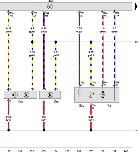
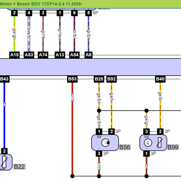
From pin 25 on the ECU, a supply voltage of 5 volts is sent to the crankshaft position sensor, fuel pressure sensor, EGR valve, throttle valve and position sensor of the turbo adjustment. Not all components are pictured above. Pin 25 is therefore for the power supply. Pin 53 for ground (seen in the schematic from HGS data) and pin 52 for the signal from the crankshaft position sensor. We can measure directly on pin 52 in the ECU plug, or we can close one breakout box to be able to measure safely and clearly in connection 52 of the breakout box.
Measuring signals with the oscilloscope:
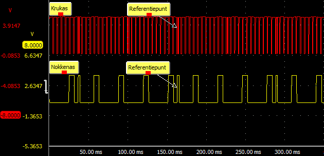
The crankshaft signal can be displayed with a two-channel measurement in relation to the camshaft signal. These signals can be used to determine whether the timing of the distribution is still correct, or whether the camshaft signal is lagging behind the crankshaft signal, for example, due to a stretched distribution chain. The figure below shows a measurement of a crankshaft signal (channel A, blue) against a camshaft signal (channel B, red).

We can recognize the following points in the signals from the crankshaft and camshaft sensors:
- Every camshaft rotation (recognition points: the two narrow blocks) four missing teeth of the crankshaft have passed;
- The crankshaft rotates two rotations when the camshaft rotates one (ratio 2:1), which means that every half rotation of the crankshaft rotates one missing tooth past the sensor.
The engine in this example (VW Golf VI) is equipped with a toothed pulse wheel with a missing tooth every 180 degrees (half a revolution). This pulse wheel is shown in the figure of the “Sensor and pulse wheel positioning” section. If you look closely, you can spot the missing teeth in this image. When the speed of the motor is increased, the frequency of the signal also increases. The pulses then come closer together. The amplitude (the height of the voltage) remains the same. A measurement on the same motor with an increased speed can be seen in the scope image below:

In case of suspected timing problems, reference points in the crank and camshaft signal can be compared with a sample signal or with another engine without any problems.
By marking two points, the difference in the number of teeth in the measured signal can be compared with the example signal. If the crankshaft signal in the measured signal is ahead of the camshaft signal (the reference point of the crankshaft shifts to the left), the timing chain may be stretched.
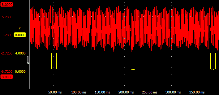
The above crankshaft signal is from a hall sensor. A motorcycle is also possible are equipped with an inductive sensor. An example of this can be seen in the measurement below. With an inductive sensor, with an increased speed, not only does the frequency increase (the pulses become closer together), but also the amplitude increases. The frequency is important for the ECU to determine the speed. The missing tooth is also clearly visible in this signal. The yellow line (coming from the camshaft sensor) gives a pulse after every second crankshaft signal. These signals can also be compared with each other.
A reference point can also be selected for the inductive crankshaft signal, e.g.:
- the camshaft signal drops to 0 volts;
- this happens two (crankshaft) teeth after the missing tooth.
With an example signal, one checks whether there are also two teeth in between. If there are three teeth in between, there is again a deviation.
Possible faults in the crankshaft sensor signal:
The crankshaft sensor may be faulty and not giving a signal. The engine management system does not receive an engine speed signal, so the engine will not start during starting. The camshaft signal may be picked up and the engine - after a long restart - can run on the camshaft signal alone.
If the pulse wheel is damaged, the motor management system may incorrectly recognize the damage as a missing tooth. After all, the damage causes a deviation in the amplitude of the alternating voltage emitted by the crankshaft sensor. An example is shown in the images below.
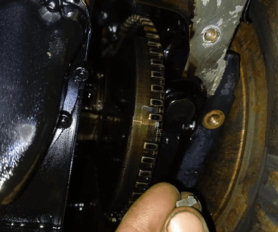
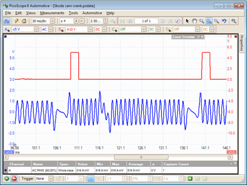
In the scope image we see twice the characteristic course of the missing tooth (to the left of the camshaft pulse). To the right of the camshaft pulse we see a disturbance in the image. The engine management reads the disturbance and can therefore inject and ignite at the wrong time. When the MMS compares the crankshaft signal to the camshaft signal, an error can be recognized and a DTC (error code) stored related to the crankshaft signal. In this case, the crankshaft position sensor may be incorrectly replaced.
The damaged tooth on the pulse wheel may have been caused by work on the engine, in which an attempt was made to block the crankshaft between the teeth of the pulse wheel with a screwdriver, instead of the starter ring on the flywheel.
