Introduction:
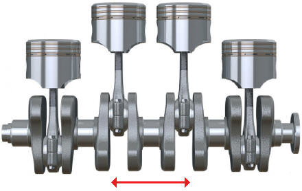
The forces from the pistons are transmitted to the crankshaft via the connecting rod. The crankshaft is a solid shaft that converts the translational movements of the connecting rod into rotational movements. A crankshaft is a long shaft with one or more projecting cranks. The connecting rods are mounted on these cranks, which in turn are connected to the pistons. When the piston moves from TDC to BDC (from top to bottom), the connecting rod is pushed downwards, causing the crankshaft to rotate.
At the front of the crankshaft are often the timing drive and the crankshaft pulley with possibly the harmonic balancer. At the rear are the flywheel and the clutch. At both ends are crankshaft seals that provide a seal between the rotating crankshaft and the engine block.
A crankshaft is a critical component in any mechanism that involves motorized movement. The crankshaft must be designed with micrometer precision because it is subjected to significant forces. Furthermore, a crankshaft rotates at very high speeds, so even a slight construction or assembly error can lead to significant imbalance and damage.
The engine speed, as displayed by the tachometer on the instrument panel, is determined by the number of rotations the crankshaft makes per minute. The crankshaft speed is measured by the crankshaft position sensor (sometimes also referred to as a TDC sensor).
Crank Pins:
To distribute the combustion forces over the entire crankshaft, the power strokes are distributed. For this purpose, the crankshaft is equipped with crank pins. These crank pins in a four-cylinder inline engine are offset by 180° relative to each other. In a V6 engine, the crank pins are often offset by 60° relative to each other.
Counterweights & Bearings:
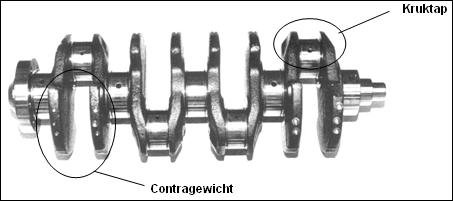
The crankshaft is also subjected to mass forces caused by the reciprocating mass movement. To compensate for these mass forces, counterweights are used to offset them. In certain engine designs, it is not sufficient to limit vibrations through counterweights alone. In these cases, balance shafts are incorporated into the engine. See the section on balance shafts.
The crankshaft is mounted in the engine block using main bearings. The crankshaft in the image above has five main bearings, but there are also crankshafts with three main bearings. Through bores in the main bearings and crankshaft, lubrication is provided to the connecting rods and pistons.
The crankshaft is also equipped with thrust bearings at a main bearing (flywheel side or center). These bearings are designed to absorb axial forces (in the longitudinal direction) on the crankshaft resulting from clutch engagement, acceleration, and deceleration.
Oil Pump:
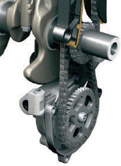
The oil pump is directly driven by the crankshaft. The drive can occur via gears, or alternatively through a chain (see image). Click here for more information on the oil pump.
Related page:
- Measuring Radial and Axial Crankshaft Play (mechanical diagnosis)