Introduction:
The climate in the car can be optimally adjusted with today’s systems. When it is cold, the interior can be heated in various ways. This heat comes from the engine’s warmth. A constant, comfortable temperature is maintained as much as possible. In high outdoor temperatures, it is nice when cool air is blown into the interior. In cars without air conditioning, this is pure outside air, but in cars with air conditioning, this outside air is significantly cooled before being blown into the interior. At too high a temperature, attention loss, slower reactions, and fatigue occur.
The air conditioning also affects humidity levels in the interior, which decrease. At too high humidity levels, you may experience a stuffy and oppressive feeling, and at too low humidity levels, you may get a dry throat and dry eyes. The most pleasant climate is with a temperature between 68 and 73 degrees Fahrenheit, with humidity between 30 and 60%, and, of course, with filtered air through an interior filter.
Ventilation Control:
Due to variations in the outside temperature or the speed of the car, the temperature in the car’s interior changes. To maintain the correct temperature, the heater and fan settings must be adjusted regularly for manual heating. Cars with automatic temperature control do not have this problem; they automatically adjust the fan speed and temperature. The control unit ensures that the set temperature is maintained. For example, if 68 degrees Fahrenheit is set and the window has been opened for a while when it is cold outside, the interior temperature sensors will detect that the interior temperature has dropped. The heating temperature will rise (to, for example, 75 degrees) and the fan speed will increase. Once the interior reaches the temperature of 68 degrees Fahrenheit again, the fan speed and outlet temperature will be lowered.
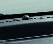
The sun sensor on the dashboard also influences the speed of the interior blower. The light intensity is measured through ultraviolet radiation in the sunlight. In bright sunlight, the interior blower will blow a larger amount of cold air into the interior. The sun sensor can be recognized by the small sphere which is usually located in the center on top of the dashboard. The image shows a sun sensor.
Temperature Control:
The temperature in the interior can be kept constant in two ways; namely by using:
- Blend-air control: Cold and warm air are mixed in the heater unit using heater valves. The cold air is the outside air temperature, and the warm air is as hot as possible (maximally heated by the coolant). By gradually opening the warm air valve, more and more warm air is added to the outside air. More information about the heater unit is described later on the page.
- Coolant control: By electronically controlling heater valves, the coolant flow through the heater core is changed. The outside air flows through the heater core. The air is heated as a result. Therefore, the air temperature depends on the coolant temperature in the heater core. More information about the heater core is described later on the page.
- Evaporator: The evaporator is a component of the air conditioning system and is described on a separate page. By allowing the warm outside air to flow through the cold evaporator, this air is cooled.
The interior blower will need to blow the air through the heater unit, heater core, and/or evaporator to achieve the desired temperature and then flow it into the interior.
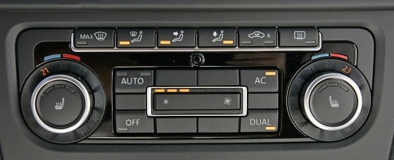
Vehicles equipped with a split climate system have an adapted heater unit allowing the outlet temperatures on the left and right sides to differ.
The next image shows a split climate control where the outlet temperature on the driver’s side is 70 degrees Fahrenheit, and on the passenger’s side, it is 73 degrees.
It is possible for rear passengers to also have one or two climate zones with a dial or display to set the temperature in two additional zones. In that case, the heater unit contains extra channels for blend-air control.
Heater Unit:
Below is the heater unit displayed. The interior blower is mounted under the heater core. The ventilation air enters the side of the interior blower and is blown through the heater core and the evaporator of the air conditioning at the top. The heater unit is located in the center under the dashboard and can, in principle, only be dismantled if the complete dashboard is removed.
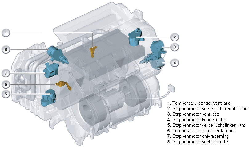
In the image above is a transparent heater unit, in which a number of stepper motors can be seen. The stepper motors control valves that regulate the airflow and temperature of the air. The image below shows the airflow through a heater unit with valves operated by the stepper motors.
The interior blower draws in outside air through the intake duct. The end of this intake duct is often located under the hood, behind the cowl panel. If the car is equipped with air conditioning, the interior blower blows the drawn-in air through the evaporator.In the evaporator, moisture and heat are extracted from the outside air, resulting in dry and cooled air reaching the heater core. When the air conditioning is turned off, the air still flows through the evaporator but will not undergo a change in temperature and moisture.
The temperature of the heater core affects the warming of the air; in the coolant circuit, valves ensure an adjusted flow rate; a lower coolant flow rate will result in less warming of the air.From the heater core, the air reaches at least three air control valves: one to the windshield, one to the dashboard air vents, and one to the footwell. The position of the valve determines how much air is blown to the respective outlet openings.
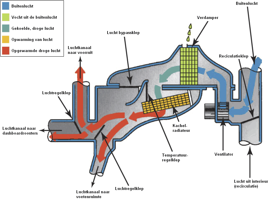
The operation of the air control valves, the temperature control valve, the air bypass valve, and the recirculation valve can be manually operated. In this case, there is a physical connection with a Bowden cable between the control sliders or knobs on the dashboard and the valves. Nowadays, we mostly see electronically controlled valves: an ECU controls the stepper motors.
An electronically controlled ventilation system often offers more options than a manual system with cables:
- multiple temperature zones: the air control valves and the temperature control valve on the driver’s side can be operated separately from the passenger’s side. In this case, the valves are dual. In luxury cars, there can even be up to four zones adjustable, doubling the number of valves and air channels in the same heater unit;
- a MAX setting to let the air conditioning function with maximum capacity: in the MAX setting, the air bypass valve opens and the temperature control valve closes: only cooled air enters the distribution housing with the air control valves. The recirculation valve will also close the outside air supply and – the already cooled air from the interior – is drawn in and further cooled via the fan;
- automatic opening and closing of the recirculation valve when the air quality sensor detects harmful substances in the drawn-in outside air.
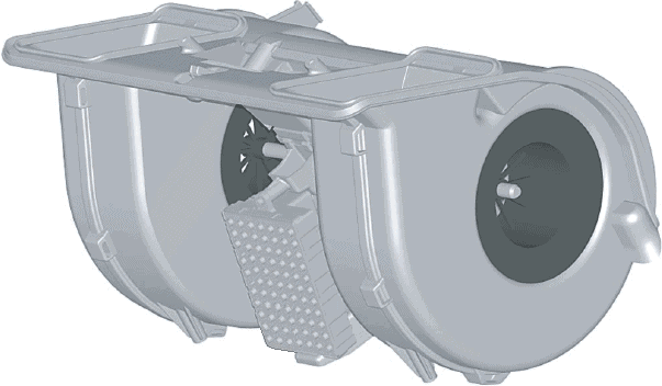
Interior Blower:
Below is an interior blower depicted. The interior blower is also referred to as a “heater motor” or “fan.” In the center of the interior blower are the blades that blow air into the interior. The ventilation air is drawn in at the top of the motor and channeled to the heater core via the side channels. The heater core is mounted directly after the interior blower in the heater unit.
The page on heater motor covers operations and different control methods.
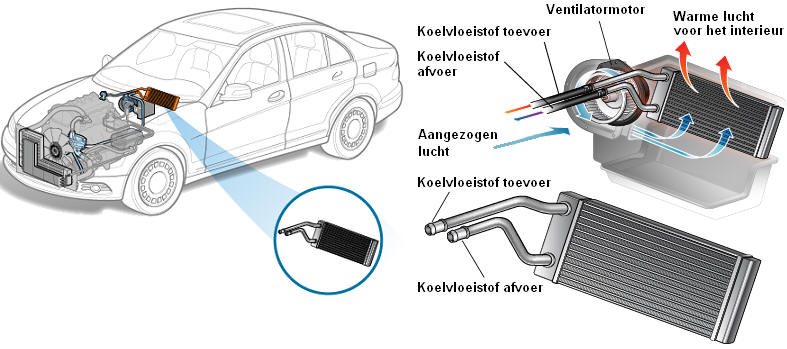
Heater Core and Valve:
The heater core warms the air blown into the interior. The heater core consists of two pipes (an intake and an outlet) that split into channels with fins placed between them. The fins provide a larger heat exchange surface.
The heater core works just like the radiator at the front of the car as a heat exchanger. Cold air flowing through the fins is heated by the coolant flowing through the channels along the fins. The heat of the coolant is transferred to the airflow. The heated air enters the car’s interior; this is the heater activated by the occupants. Because the warm air blown into the interior by the interior blower depends on the coolant temperature, it is logical that the heater remains cold right after starting the engine. The heater is only fully functional when the engine reaches operating temperature.
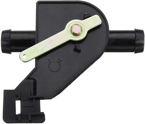
The occupants can adjust the heater to be warmer or cooler. By operating the heater, the opening angle of the heater valve changes. The heater valve regulates the amount of coolant flowing through the heater core. The size of the coolant flow ultimately determines the air temperature.
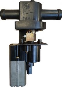
The image below shows a heater valve with pipes on both sides where the coolant hoses are slipped on. In the center of these pipes, there is a rotating valve that blocks or allows coolant flow depending on the opening angle. The valve is operated by a lever, also shown in the image. The lever can move a maximum of 90 degrees; in extreme positions, the valve is fully open or closed. A Bowden cable to the heater control unit (mechanical) or an electric/stepper motor (electronic) is connected to this lever. More on this later.
The control principles of the heater valve are described below:
Heater Valve Fully Opened:
- Large coolant flow.
- The coolant is not easily cooled by the airflow.
- The material of the heater core remains very warm.
- The air blown into the interior is warm as a result.
Heater Valve Partially Open or Closed:
- Small or no coolant flow.
- The coolant cools more easily by the airflow.
- The material of the heater core cools down.
- The air blown into the interior is lukewarm or cold, as the outside air temperature is barely affected.
The images below show the components:
- The principle operation of the actuator (left);
- The heater valve and actuator in mounted condition (center);
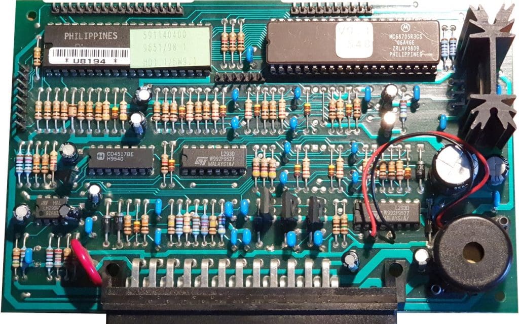
- The ECU of the climate control (right).
The relevant actuator and ECU are from a Maserati Quattroporte from 2001. The actuator is of the type DC electric motor with brushes. It is controlled by an ECU through a duty cycle. The electric motor drives the output shaft and the slider that moves over the contact disc via various gear transmissions. The disc is provided with a 5-volt supply and ground. Depending on the slider’s position, a signal is sent to the ECU, determining the position of the output shaft and hence the heater valve. In the current position, the signal voltage is 4.5 volts. As the output shaft and the slider rotate counterclockwise by a few degrees, the signal voltage drops to 4.4 volts or lower. At extreme positions, the signal voltage will be between 0.5 and 4.5 volts.

The ECU controls the heater valve until the mechanical end stop is reached. Due to the low torque of the electric motor, the rotation is halted by this end stop, and the signal voltage of the slider on the contact plate remains constant. The ECU will cease the control.
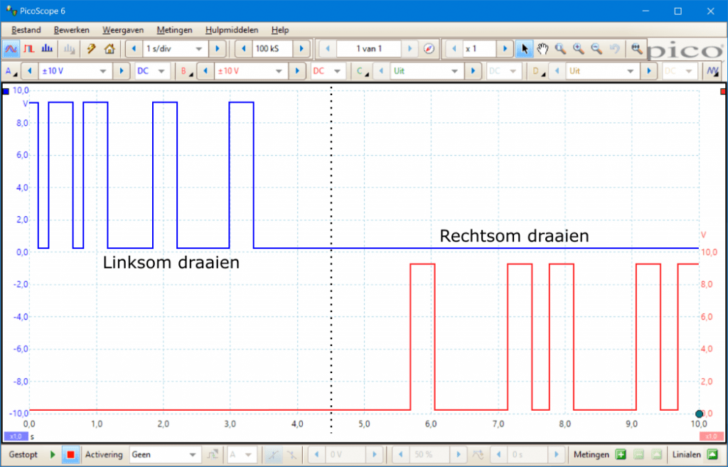
The electric motor is supplied with voltage and ground. These are controlled by the ECU through PWM control. The following oscilloscope image shows the control signals measured on the plus and ground connections of the electric motor during clockwise and counterclockwise rotation.
- Clockwise rotation: the ECU sends a block signal to the plus of the electric motor. The ground is constantly 0 volts;
- Counterclockwise rotation: the polarity of the electric motor reverses.
It may happen that the axle in a heater valve becomes harder to move due to aging. The ECU may “think” that the end stop is reached due to this mechanical resistance, thus ending its control. A new article will be published soon where there was a fault in the control with the above ECU and actuator. After diagnosing and repairing the circuit board, the system worked properly again. The symptoms, cause, and solution will be illustrated with images.
Besides this version with a DC motor and PWM control, many heater valves and heater cores are controlled by a stepper motor.
When the heater is activated immediately in winter and the interior blower is set to level 4, the engine will also reach operating temperature less quickly. This is because the passing air cools the coolant again. This is not desirable because we, of course, want the engine to warm up as quickly as possible. Therefore, it is advisable to activate the heater only after driving a few miles.
With a parking heater or electric auxiliary heating, the heater core and the combustion engine’s cooling system can be brought to temperature faster.
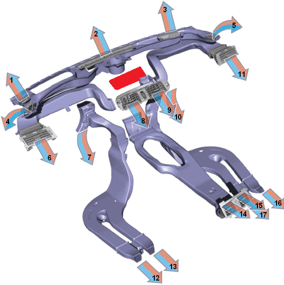
Ventilation Ducts:
In the image below, the ventilation ducts and outlets are displayed. Normally, this is not visible because the dashboard, center console, and carpet are mounted over them. The stepper motors of the heater valves in the heater unit regulate the airflow to different directions (to the windshield, to the left or right air vents, or to the footwells). There is a constant airflow to the rear compartment. The rear air vents in the center console can be closed manually.
Numbers 1, 2, 3: Air opening to the windshield (including for defrosting)
Numbers 4, 5: Defrosting of both front door side windows
Numbers 6, 8, 9, 11: Air vents for the driver and passenger compartment
Numbers 7, 10: Air openings for footwells of driver and passenger compartment
Numbers 12, 13, 16, 17: Air openings for footwells of rear passengers
Numbers 14, 15: Air vents in the center console for rear passengers