Topics:
- Introduction
- Measurement without Fault
- Diagnosing Sensor Wiring
- Fault 1 – Open Signal Wire
- Fault 2 – Open Power Wire
- Fault 3 – Open Ground Wire
- Fault 4 – Transition Resistance
- Fault 5 – Short Circuit Between Power and Signal Wire
- Fault 6 – Short Circuit Between Power and Ground Wire
- Fault 7 – Short Circuit in Sensor C
- Fault 8 – No Power Due to Faulty ECU
- Fault 9 – Open PWM Signal Wire
- Repairing an Open Power Wire
Introduction:
When we suspect a fault, we first read out the car. The fault code provides us with a direction to investigate further. If no fault codes are stored in the fault memory, we check for anomalies in the live data. See the On Board Diagnostics page.
If the fault code concerns a sensor, it doesn’t necessarily mean the sensor is defective. To rule out wiring and/or connector issues, we use wiring diagrams and measurement equipment to exclude certain possibilities. This page outlines several potential situations and shows that the fault code description may differ from the actual cause.
Measurement without Fault:
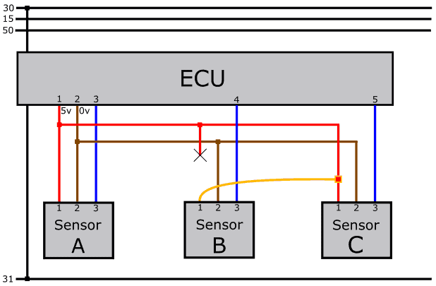
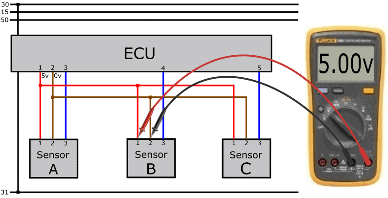
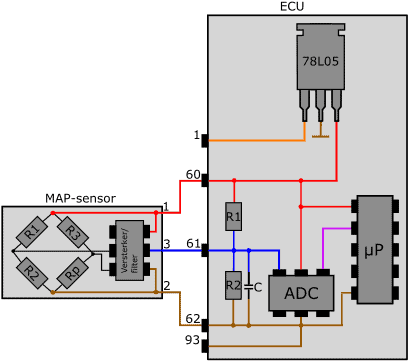
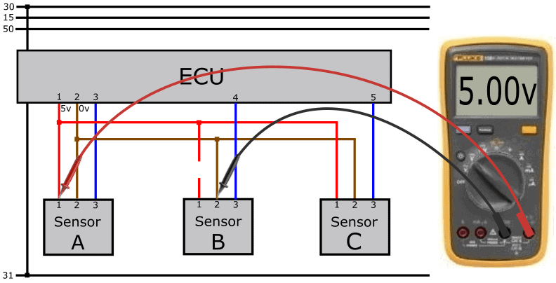
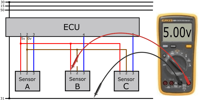
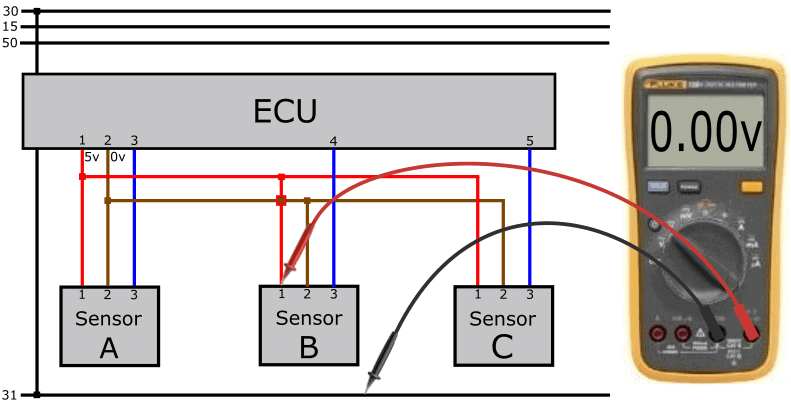
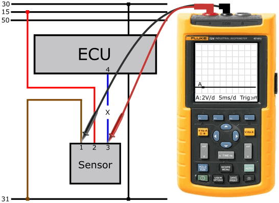
The following image shows the measurement of the supply voltage and ground of an active sensor.
The active sensor receives a positive (5 volts) and a ground through the control unit. In the measurement shown next to this image, the power supply is in order.
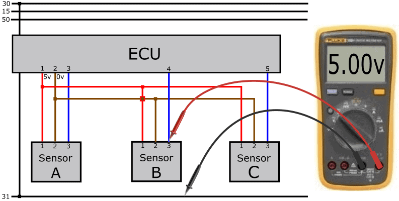
The signal sent through pin 3 of the sensor should be between 0.5 and 4.5 volts. To measure this, connect the red probe to pin 3 and leave the black probe on the ground (pin 2).
Besides active sensors, we also work with passive and intelligent sensors. Read more about it on the page: sensor types and signals.
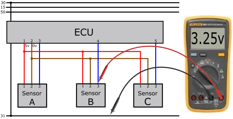
The sensor uses the 5-volt supply voltage to generate the signal. The signal should range between 0.5 and 4.5 volts. The ECU reads the voltage level (or, in other cases, the frequency) and translates this into a value. For instance, the value of the boost pressure sensor: at a turbo pressure of 1.5 bar, the sensor sends a 3.25-volt signal to the ECU.
In this measurement, the signal voltage relative to ground is measured and is okay.
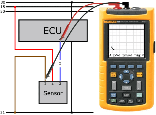
Using a breakout box, we can measure in the ECU connector. We then know which voltages the ECU is sending and receiving.
In the following measurement, we again measure 3.25 volts, but this time at the ECU input. This means the signal wire is okay: the voltage is transmitted 1:1 from the sensor to the ECU.

The sensor signal will never be 0.0 or 5.0 volts. A certain range is always maintained, often between 0.5 and 4.5 volts. The sensor will not send voltages lower than 0.5 or higher than 4.5 volts. In case of sensor or wiring defects, the ECU can recognize from the voltage level if the value is within or outside the measurement range:
- Voltages lower than 0.5 volts: the ECU generates a fault code with the description: “sensor X, short circuit to ground” or “ground fault”;
- At voltages higher than 4.5 volts, “positive short” is indicated in the fault code description.
Active sensors can also send a digital signal. Often, these sensors are not powered by the ECU but through terminal 15. In most cases, we deal with a PWM signal.
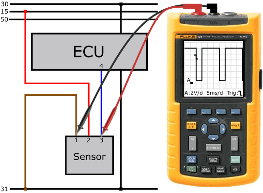
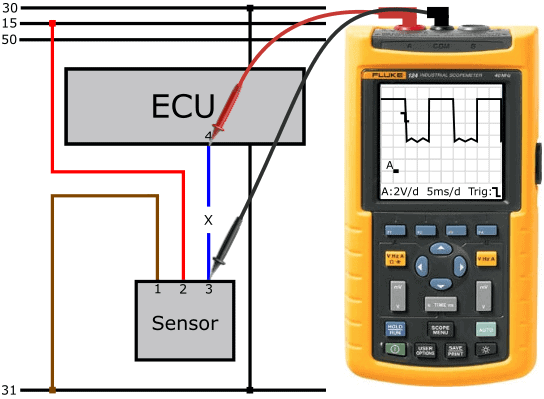
The following image shows part of the diagram where an active sensor has an external power supply, and the signal wire is connected from pin 3 of the sensor to pin 4 of the ECU. An oscilloscope measures the voltage change of the sensor with respect to the ground connection.
The scope is set to 2 volts and 5 milliseconds per division. The duty cycle is 50%.
In the paragraph: Fault 9 – Open PWM Signal Wire, we cover the steps to make a proper diagnosis.
Diagnosing the Sensor Wiring:
Before diagnosing sensors, we must be aware of the type of sensor (passive, active, intelligent) and how the sensor sends its signal to the control unit (analog or digital, in the form of AM or FM). After consulting the wiring diagram, we can estimate what voltages we will measure on the wiring.
The following paragraphs outline possible faults that can occur in practice. Instead of starting with “the customer’s complaint”, we immediately state the cause; e.g., an open wire, a short circuit, etc. This is about gaining insight into measurement techniques. How do you act in case of a fault? And with which measurements can you determine the cause?
If you master the measurement techniques and are curious about a case, visit the page: Case: Fuel Pressure Sensor Fault Short Circuit to Positive
Fault 1 – Open Signal Wire:
With an open signal wire, the sensor signal voltage cannot reach the ECU. In this paragraph, you can read what you will measure at both the sensor and ECU connections in this situation.
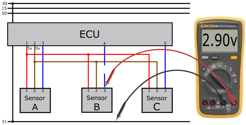
We perform the following measurements on the active sensor and obtain the following readings:
- Power wire (pin 1) relative to sensor ground (pin 2) measures 5 volts;
- Signal voltage relative to ground measures 2.9 volts.
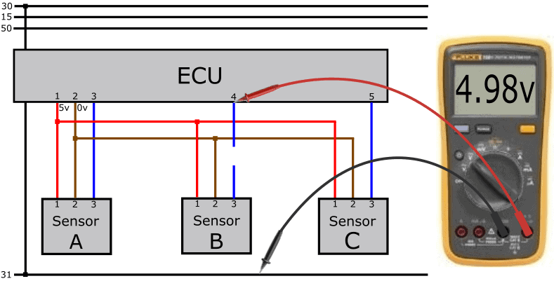
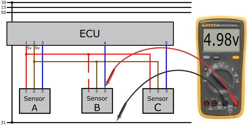
The power supply and generated sensor signal are fine. However, the sensor signal does not reach the ECU due to the interruption. To measure the voltage at the ECU input, we use a breakout box.
Using a breakout box, we perform a measurement on pin 4 of the ECU relative to ground (or pin 2 of the sensor). We measure a voltage of 4.98 volts.
The voltage on the ECU side is therefore higher than the voltage sent by the sensor. A circuit in the ECU is responsible for the output voltage of 4.98 volts. This partly pertains to signal processing and also to recognizing interruptions.
The ECU now measures its own output voltage and recognizes this, due to the supply voltage of 4.98 volts, as a positive short.
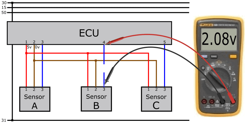
Then we measure the voltage difference across the wire between the ECU and the sensor. The voltage difference should be nearly 0 volts in a fault-free situation.
In this case, we measure a voltage difference of 2.08 volts; namely, 2.9 volts (sensor) versus 4.98 volts (ECU).
The voltages can lead you astray.
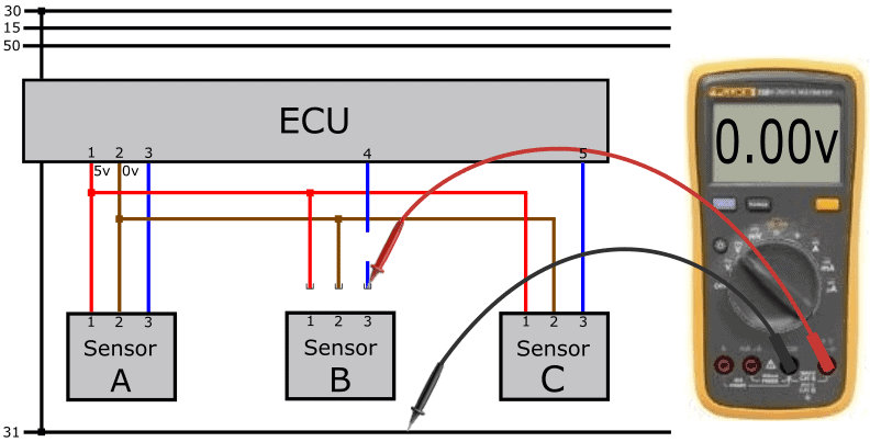
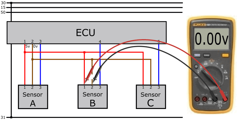
Disassemble the sensor connector. If there was no interruption in the wire, we would measure 4.98 volts from the ECU in the disassembled connector. Now we measure 4.98 volts on pin 4 of the ECU but 0 volts in the disassembled connector.
In this case, we can already conclude that the signal wire is open.
With an open signal wire, the voltage on the ECU’s signal input is approximately 5.0 volts. On the page:sensor types and signals, in the paragraph: “power supply and signal processing” you can read how the ECU processes the signal from the active sensor. With that knowledge, you can better understand how to deal with faults like the open signal wire.
The 4.98-volt voltage is generated in the ECU. Between the positive wire (coming from the 78L05) and the ADC, there are several resistors that pull the signal voltage to 5 volts when no voltage comes in via the signal connection. The ADC measures this voltage and converts it into a digital signal. The ECU thus receives a signal over a voltage that is out of range and generates a fault code.
Note: For similar faults, the voltage is not always exactly 4.98 or 5.0 volts!
Visit the page: Case: Fuel Pressure Sensor Fault – Short Circuit to Positive for a fault where this voltage value differs.
Fault 2 – Open Power Wire:
Between the junction of the positive wire among the three sensors and the sensor connector, there is an interruption. The 5-volt supply voltage cannot reach the sensor. Without power supply and ground, the sensor cannot function.

Since we measured the power and ground at the connector in the previous measurement, we still need to rule out which of the two wires has a problem. Therefore, we measure the positive on another sensor in the same power circuit. The ECU can, of course, also be used if a breakout box is available.
On pin 1 of sensor A relative to the ground of sensor B, we measure 5 volts. That means sensor B’s ground is okay.
When no current flows through the active sensor’s electronics due to the open power wire, we measure 4.98 volts on the ECU’s signal input. We have a similar situation as with the open signal wire: the internal resistors in the ECU pull the signal voltage up to 4.98 volts. Because the signal wire is intact in this case, we also measure the 4.98-volt voltage on the sensor connector.
In cases where the voltage is slightly above 5.0 volts, the voltage regulator’s output may have been lifted. See the paragraph: “power supply and signal processing” on the page: “sensor types and signals“.
Fault 3 – Open Ground Wire:
In this case, it is not the positive but the ground wire that is open. The sensor receives a 5-volt power supply, but since we are measuring relative to an open wire, the voltmeter has no reference voltage and reads 0 volts.
By moving the negative probe to the body or battery ground, the voltmeter reads 5 volts.
When we connect the negative probe to the ground connection of sensors A and C, we should also measure a 5-volt difference. If we measure 5 volts at pin 2 of sensor A but not at sensor C, the interruption is between sensor A and B, between the first two junctions.
As with the open signal and positive wire, we now measure a voltage of 4.98 volts on the signal wire.
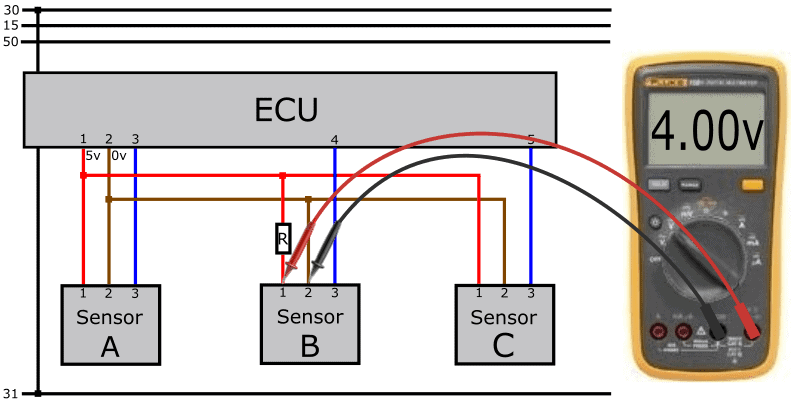
Fault 4 – Transition Resistance:
The previous paragraph already discussed voltage loss due to transition resistance. In the next diagram, we see a resistor in the power wire. When current flows through the power wire, the transition resistance causes a (presumably) low voltage on pin 1 of connector B. We measure 4 volts instead of the expected 5 volts.
The stored DTC description in this case may be: “signal lower limit exceeded”.
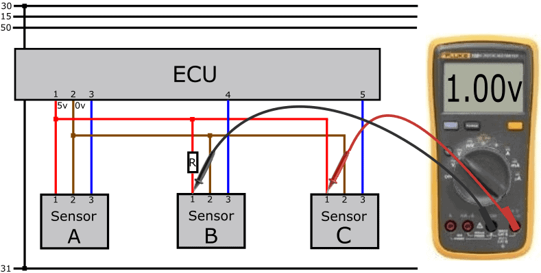
If we measure pin 1 of connector B relative to pin 1 of connector C, we should ideally have a difference of (5-5) = 0 volts. Now we see a 1-volt difference.
Because the voltage loss is only present in the wire of sensor B and not sensor C, we can assume that the wire between the horizontal wire junction in the diagram and the connector is not in order.
Fault 5 – Short Circuit Between Power and Signal Wire:
A possible fault in the wiring is a short circuit. Short circuits occur in the following situations:
- between the power wire and the signal wire (positive short);
- between the ground wire and the signal wire (ground short);
- between any of the three wires to each other and/or to the body (ground short);
In this diagram, we see a short circuit between the signal wire and the positive wire (positive short). We measure a signal voltage equal to the supply voltage of 5 volts.
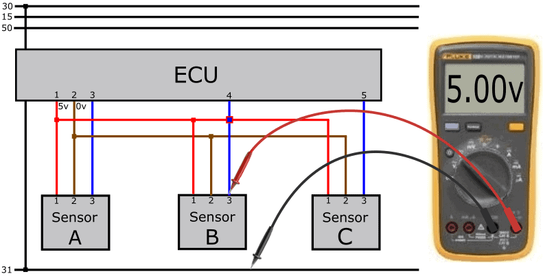
When measuring 5 volts on pin 3 of the sensor and pin 4 of the ECU, the problem may be internal to the sensor. To rule this out, we use an Ohm meter to check for short circuits in the wiring. For a safe and correct measurement, switch off the ECU, disconnect the ECU connector, and disconnect the connectors of the sensors connected at the junctions. Due to the short circuit, we measure a connection with the Ohm meter.
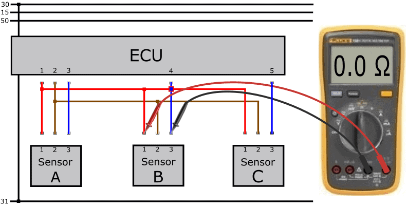
This is 0.0 Ohms in this case because the wires are connected. In reality, this value can be a few Ohms higher. When no short circuit is present, the ohmmeter displays OL or 1. (indicating infinite resistance) because there is no electrical connection between the wires and probes.
Fault 6 – Short Circuit Between Power and Ground Wire:
With a short circuit between the power and ground wires, the ECU cuts off the power from pin 1. All sensors powered through pin 1 will stop functioning, and multiple sensor fault codes will be stored.
On the signal wire, we also measure a voltage of 5.0, originating from the ECU.
To rule out a short circuit, we disconnect the ECU and all sensors in the respective circuit as described in the previous paragraph. Using an ohmmeter, we measure the resistance between the red and brown wires.
Fault 7 – Short Circuit in Sensor C:
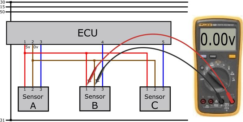
When measuring the supply voltage relative to ground, we again measure 0 volts. In the previous fault, the short circuit was in the wiring. In this case, the short circuit is internal to a sensor.
We disconnect the connectors of the sensors seen in the diagram one by one. When unplugging the sensor C connector, we no longer have a short circuit, and the ECU will restore the positive wire to 5 volts. In some versions, this occurs automatically; in others, a terminal change is needed.

Fault 8 – No Power Due to Faulty ECU:
In rare cases, the ECU can be the cause of the missing supply voltage. Internally, a circuit is damaged and no 5 volts is sent out.
The ECU often gets blamed for being defective. In most cases, there is another root cause. Therefore, first, check for possible interruptions and short circuits in the wiring and connected sensors. To eliminate an internal defect in the ECU as the cause, we check all ground connections of the ECU.
In a comprehensive engine management system, we see multiple circuits in an ECU, each with its own ground wire. Sometimes we find up to eight ground wires in a single connector. When one pin in the connector makes poor contact, or one ground wire in the harness is open, that circuit fails. Therefore, measure with a test lamp (positive on the battery, negative on each ground connection in the ECU connector) to see if the ground is okay. The test lamp should glow equally bright on each ground. If one ground connection does not light up, you may have identified the cause, and the ECU is not faulty.
Fault 9 – Open PWM Signal Wire:
So far, we have discussed analog voltages measured with a multimeter. When dealing with a digital signal, a multimeter is no longer adequate. We then use an oscilloscope. The following text discusses the oscilloscope in the images below. Here we see the Fluke 124 with a modified screen display.
The reason for performing this measurement is the fault description that can be translated from the fault code. The description reads: “sensor signal open”.
In the scope image, a constant voltage line of 0 volts is visible. This means there is no voltage difference between the probes. If you measured that the power and ground wires of the sensor are good (pin 2 relative to 1), in this case around 13 volts, there’s an issue with the signal wire. Note that the sensor can transmit the information in two ways:
- The sensor sends a positive voltage to the ECU (usually an analog voltage);
- The ECU sends a voltage, which the sensor grounds on a timed basis (using PWM; a digital signal).
In the example, the signal voltage on the sensor side is 0 volts, so we assume method 2.
Due to the open signal wire, the sensor receives no voltage from the ECU.
We measure pin 4 of the ECU relative to pin 1 of the connector. The voltage is 12�0volt. With these measurements, we have determined that the sensor input of the ECU is fine.
The ECU evidently sends a constant voltage, but it does not reach the sensor. Therefore, the sensor has no voltage to switch to the ground.
In the next measurement, we connect the probes across both ends of the signal wire. This determines the voltage difference in an active state across the wire. The voltage should be 0 volts in a faultless condition. However, in the active part of the square wave, we see a voltage of 12 volts. When we measure the full supply voltage in the most positive part of the square wave, we often have a case of an open wire. This is also the case now: the ECU’s output voltage (pin 4 to ground) is 12 volts.
Furthermore, in the low part of the square wave, there is a deviation: the line drops to about 5 volts, remains constant for 10 milliseconds with a ripple, and then rises again to 12 volts. Because the oscilloscope is now in series between the pull-up resistor in the ECU and the pull-down resistor in the sensor, a series circuit is created. The scope has a high internal resistance, which affects the signal. For this reason, the signal is unusable.
Although a loaded voltage measurement is sufficient for a good diagnosis, it does not hurt to use a resistance measurement to show that there is indeed a broken connection in the wire. In this case, we measure an infinitely high resistance (OL or 1.)
After repairing the signal wire, we again measure signal voltage relative to ground. Note: we measure relative to ground here, so the “active” part of the sensor in the PWM signal is now reversed…
In this scope image, we see that:
- the maximum voltage is 12 volts. Here the sensor is not active: the voltage on the signal wire is not pulled to ground.
- the voltage drops to 1 volt. Here the sensor is active: the sensor grounds the ECU voltage through the sensor electronics.
Within the sensor, there is an electronic circuit that still uses 1 volt. With this voltage, the ECU can also recognize that the sensor is switching properly. The ECU can determine if the sensor is functioning well based on the voltage levels:
- voltage over a longer time is equal to or higher than 12 volts:
ECU recognizes an open or positive short; - voltage below 1 volt: ECU recognizes a ground short.
Repairing an Open Power Wire:
Of the five faults described in the previous paragraphs, these can often be fixed fairly easily.
Cut the wire with the open circuit or transition resistance as short as possible in the harness.
Apply insulation if needed. Find the nearest sensor connected in the same power circuit. With active sensors, you can easily find this in an electric diagram. In the diagram, the nearest sensor is C. Neatly solder a new wire to the positive wire.
Always use shrink tubing to prevent future issues from moisture ingress. If you seal it with electrical tape, new problems will arise within a short time!