Thevenin equivalent circuit:
The Thevenin theorem is a widely used method for simplifying complex circuits. Any circuit with one or more voltage sources and a number of resistors can be replaced by one voltage source Eth and one internal resistance Rth. The Eth and Rth calculated are important for ultimately determining the voltages across the resistors and the current through the circuit.
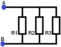
Circuit 1:
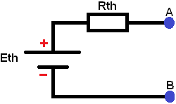
Displayed here is a Thevenin equivalent circuit. Eth represents the voltage source and Rth the equivalent resistance. Any circuit with multiple voltage sources and multiple resistors can be simplified to this circuit.
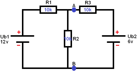
This circuit with 2 voltage sources and 3 resistors is calculated and simplified into the Thevenin equivalent circuit. In the following steps, the voltages and currents in the circuit are calculated to determine the voltage UAB (the voltage at points A and B).
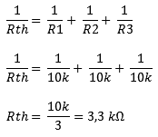
Step 1:
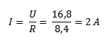
Determine the equivalent resistance of the below circuit where UB2 is short-circuited. The formulas show the elaboration of the equivalent resistance and the current strength.
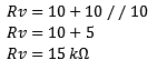
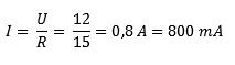
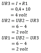
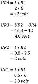
Short one voltage source. In this case Ub2 (see image below). Remove the voltage source from the circuit. From the voltage source Ub1, the current of 0.8 A will flow. First, the voltage across resistor R1 must be calculated because the current encounters it first.
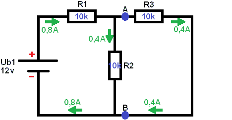
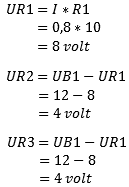
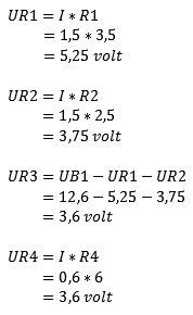
It is important not to calculate UR2 the same way as UR1, because the voltage UR1 still needs to be subtracted. This is because the voltage is lost through the consumers. Initially, the voltage in the circuit is 12 Volts, but when the negative terminal is reached, the voltage must be 0 volts. This is not the case with current! All the current that leaves the battery is distributed throughout the entire circuit and comes back together at the negative terminal of the battery.
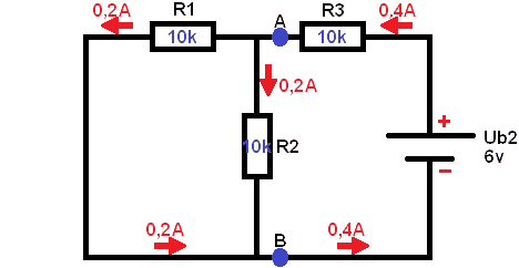
Step 2:
Now Ub1 is removed from the circuit and Ub2 is replaced. Now the equivalent resistance and current strength as a result of Ub2 must be determined.
Step 3:
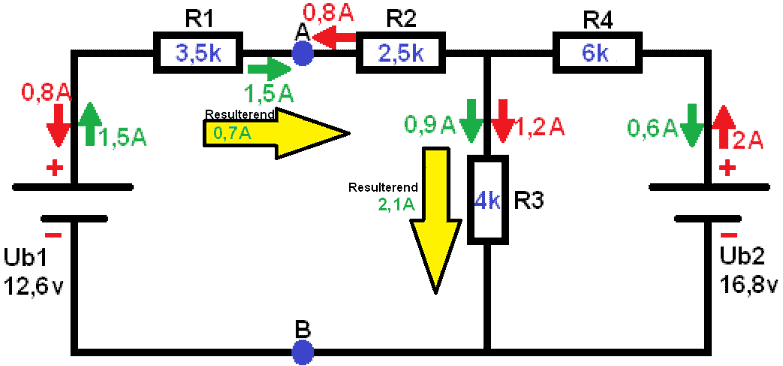
Now it is time to restore the circuit to its original state:
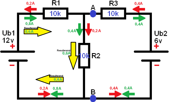
The current direction of both circuits is displayed; the green is from the first and the red from the second circuit. If the current direction is opposite (the arrows face each other), there will be a resulting current left.
0.2 A to the right and 0.8 A to the left: results in 0.6 A going to the left (by simply subtracting 0.8 and 0.2 from each other).
0.4 A to the right and 0.4 A to the left: cancel each other out. The resulting current is 0.
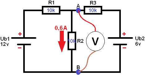
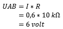
The current across resistor R2 is known. Now the voltage UAB can be measured. The voltage UAB is parallel to R2, so they are the same. In principle, the resulting voltage across R2 is now also measured: UAB = UR2.
Step 4:
To create a Thevenin equivalent circuit, step 4 still needs to be executed. UAB open is known. This is also referred to as the open terminal voltage, Eth, or Uth (in this example, Eth is used). Eth stands for the Thevenin voltage.
Calculate Rth:
Eth is known. So in the final Thevenin equivalent circuit, Eth and Rth must be indicated:
In the circuit below, the Thevenin equivalent circuit is displayed as it is officially intended. Any circuit with one or more voltage sources and resistors can be simplified to this circuit:
Eth = 6 volts
Rth = 3.3 kf
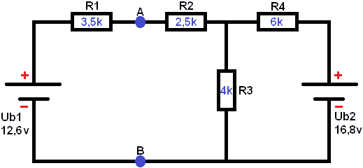
Circuit 2:
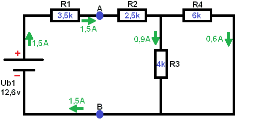
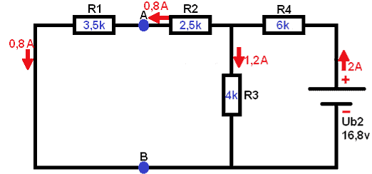
Below is a diagram with 2 voltage sources (Ub1 of 12.6v and Ub2 of 16.8v). The voltage UAB must be determined (the voltage on the blue dots). Through the following steps, the voltages across the resistors and the currents throughout the entire circuit are calculated. Subsequently, the voltage across A and B can be calculated again.
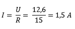
Short 1 voltage source. In this case Ub2. Remove the voltage source from the circuit. From the voltage source Ub1, the current of 1.5 A will flow. First, the voltage across resistor R1 must be calculated because the current encounters it first.
Lorem ipsum dolor sit amet, consectetur adipiscing elit. Ut elit tellus, luctus nec ullamcorper mattis, pulvinar dapibus leo.
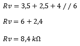
Step 2:
Determine the equivalent resistance of the below circuit. Now Ub1 is removed from the circuit and Ub2 is replaced. In this case, the equivalent resistance is again
Step 3:
Now it is time to restore the circuit to its original state:
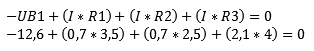
With this data, the voltage UAB can be calculated. A current of 0.7mA flows over the resistor R1 of 3.5kf. Because the left part of the circuit (the part of Ub1) is a closed circuit, UAB is calculated with the voltage of Ub1. Ub2 is not involved here because it is another closed circuit. This can be easily seen by applying Kirchhoff’s law: All voltages in a closed circuit are equal to 0. We can prove that:
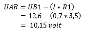
Calculate voltage UAB:
Related pages: