Subjects:
- Preface
- Types of resistors
- Color coding
Preface:
Every electrical consumer has an (internal) resistance. Although an electrical conductor, such as wiring, has a small resistance value, it is still there specific resistance which depends on the material, dimensions and temperature. Each consumer also has a resistance value. The resistance value ultimately determines how much current flows through it.
Resistors can be found as components in almost all electronics. Resistors are also used in automotive engineering in electrical circuits, e.g. on printed circuit boards. A resistor limits the electrical current through a circuit and converts the electrical energy into heat:
- increasing resistance: less and less current flows through the circuit;
- decreasing resistance: the current strength increases.
The resistor on a printed circuit board is connected in series with a component in which the current must not rise too high.
The unit of resistance is ohm and is denoted by the Greek letter omega Ω. As a letter and symbol for resistance we use the R (derived from the English translation: Resistor).
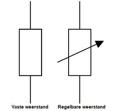
A resistor can be designed as a fixed resistor or as an adjustable resistor. In the figure below, the symbols of these two types of resistors are shown. The symbol consists of a rectangle with a line on either side. Often in a diagram in or next to the rectangle the letter R is stated with the resistance value in ohms.
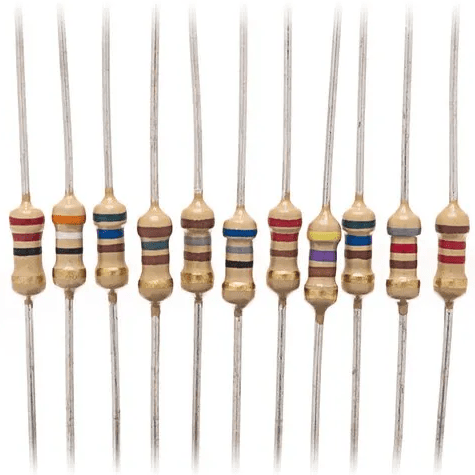
- Resistors with a fixed resistance value can often be recognized by the color rings around the housing. The resistance value can be found out on the basis of the color rings;
- Variable value resistors are usually adjustable with a dial. This type of resistor can also be designed as potentiometer, which is often used as a position sensor.
The following section shows the different types of resistors that we can encounter in the automotive industry.
Types of resistors:
The figure below shows an overview with twelve different types of resistors. Below the image, the structure and application of the type of resistor is described per category.
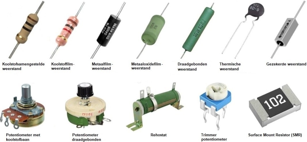
The commonly used resistors in automotive and automotive training practicals are shown below. The structure of the materials that make up the resistors is described for each resistor.
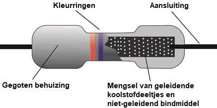
Resistor with Carbon Compound:
This resistor has a cylindrical shape and contains color rings with which the resistance value can be found. The resistance element consists of carbon powder or graphite powder, mixed with ceramic clay. The resistor is covered with a molded plastic housing. The resistors are known for poor temperature coefficient and low reliability in terms of noise and accuracy. This type of resistor has been replaced by the film type.
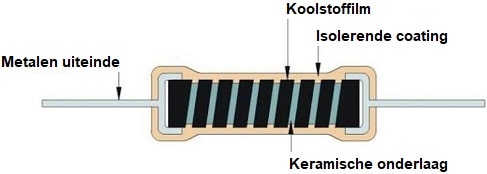
Carbon Film Resistors:
The carbon film resistor consists of a ceramic substrate with a thin layer of carbon film on top. The resistance value is determined by the groove.
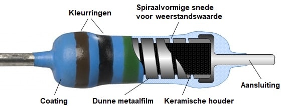
Metal Film Resistor:
The metal film resistor is very similar in construction to the carbon film resistor. However, with this type of resistor, a metal film is applied to a ceramic layer.
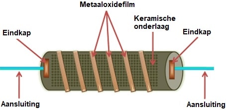
Metal Oxide Film Resistor:
The construction of this resistor has many similarities with a metal film and carbon film resistor. Instead of metal or carbon, a metal oxide film is deposited on the ceramic substrate.
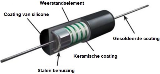
Wirewound Resistance:
The wire wound resistor contains a metal resistance wire wound over ceramic material. The resistance depends on the thickness of the metal wire. The accuracy of the wire wound resistor is high. The temperature resistance coefficient is so low because of the resistance wire that this resistance is very suitable for applications where high power is required.
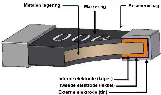
SMD resistor:
The SMD resistor is often referred to as a “chip resistor” and consists of a metal alloy (consisting of metal oxide or a metal film) with a three-layer electrode structure on both sides. The length, thickness and the material used determine the resistance value. The inner electrode is connected to the metal alloy. The The middle electrode is made of nickel and its function is to ensure heat resistance during soldering. The outer electrode is a tin layer and makes the resistor suitable for soldering directly to the printed circuit board.
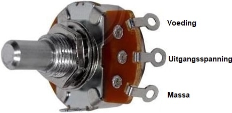
Potentiometer:
The potentiometer behaves like a variable resistor. The resistance value depends on the position of the runner on the carbon track. When a power supply (often 5 volts) and ground are connected, the output voltage is between 0,5 and 4,5 volts, depending on the position of the rotary switch.
More information can be read on the page: potentiometer.
Properties of resistors:
If we want to use resistors, we have to choose the type of resistor that is suitable for the characteristics: is high accuracy needed at low power, or is high power needed where the noise on the system is not an issue?
- Maximum voltage: The maximum voltage of a resistor must not be exceeded. When that does happen, there can be a breakdown. This can affect the resistance value;
- Maximum power: if the resistance's power is exceeded, the temperature will rise too high. The resistance value can change. The capacities of carbon resistors are often 0,25 Watt to 1 Watt and of wired resistors 3 Watt to 20 Watt.
- Tolerance: A resistor never has the exact value stated on the case. However, a percentage is stated on the housing which indicates the deviation. This deviation in percentages is caused by the precision in the production process. A 120 ohm resistor with a 5% tolerance can be a minimum of 114 ohms and a maximum of 126.
Color coding:
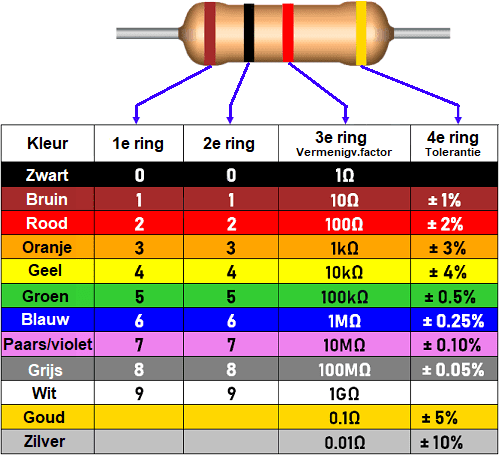
The value and tolerance of a resistor is marked on a carbon or wire wound resistor by color coding (color rings) on the resistor housing. It is important to start reading from the right side:
- the first ring is often closer to the end of the housing;
- the first ring is often wider;
- the last rings can be silver or gold. These colors are not used for the first rings.
When a resistor has four rings, the meaning of the rings is as follows:
- Ring 1 and 2: resistance value;
- Ring 3: multiplier;
- Ring 4: tolerance.
In the picture we see a resistor with the 1st ring brown, 2nd ring black, 3rd ring red and the fourth ring gold. In the table we read the numbers: 10*100 ± 5%. The resistance value is 1000 Ω (1 kΩ) with a tolerance of 5%. The actual value is between 950 and 1050 Ω.
We find resistors in series. We often come across the E12 series, in which the resistance values increase as follows:
10, 12, 15, 18, 22, 27, 33, 39, 47, 56, 68, 82.
These values can be divided or multiplied by ten, for example 100, 120, 150, 180. Or, 1000, 1200, 1500, 1800. There are no 130 ohm resistors.