Topics:
- Series and Parallel Circuits Overview
- Series Circuit in Practice
- Series Circuit: Calculating Equivalent Resistance
- Series Circuit: Calculating Current and Voltage Drops
- Parallel Circuit: Calculating Equivalent Resistance
- Parallel Circuit: Calculating Branch Currents
- Combined Circuit
- Combined Circuit Exercise
Series and Parallel Circuits Overview:
On this page, we look at series circuits, parallel circuits, and combined circuits as applied in automotive technology. Knowledge of basic electronics is required.
Series Circuit:
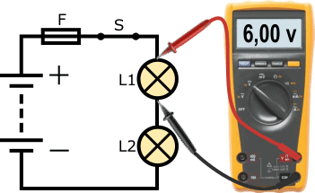
The following circuit shows a connection with a 12-volt battery, a fuse (F), a closed switch (S), and two bulbs (L1 and L2). The ground wire of lamp L1 is connected to the positive wire of lamp L2. This is called a series circuit.
The current through both bulbs is the same. The voltage is divided. Since in the example two lamps with the same power are used, the battery voltage of 12 volts is divided into 6 volts per lamp. Therefore, lamps in automotive technology are not placed in series. Additionally, if one bulb is defective, the entire circuit is interrupted, causing the other bulb not to light either.
Parallel Circuit:
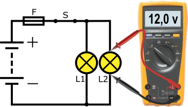
In automotive technology, we almost always deal with parallel circuits. The following circuit shows the connection where both lamps L1 and L2 have their own positive and ground wires. The voltage across each load is equal to the battery voltage; this is visible in the voltmeter reading. The same bulbs are used in this example as in the series circuit; here, however, they shine brighter because the bulbs now receive more voltage and current.
Another characteristic of a parallel circuit is that if one bulb is defective, it does not affect the operation of the other bulb.
Series Circuit in Practice:
As described in the previous paragraph, in automotive technology we almost always deal with parallel connected loads. We want as much voltage and current as possible to make the loads work, and as little risk of malfunctions if one of the loads becomes defective.
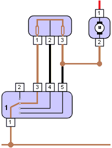
In practice, however, we find loads that are placed in series to perform their task. An example is the interior fan / heater motor. To regulate the fan speed, a resistor is placed in series in the ground connection between the electric motor and the ground point. This is also called a ballast resistor.
By placing one or more resistors in series, the loss increases, and the voltage across the electric motor decreases.
Read more about this on the page: ballast resistor of the interior fan.
An unwanted series circuit can also be present; for example, a transition resistance in a positive or ground connection resulting in voltage loss (see the page “measuring with the multimeter“).
Series Circuit: Calculating Equivalent Resistance:
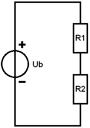
Every electrical load has an internal resistance. A high resistance results in a low current; in other words, the resistance determines the current. The supplied voltage is equal to the source voltage (Ub, that is, the battery voltage).
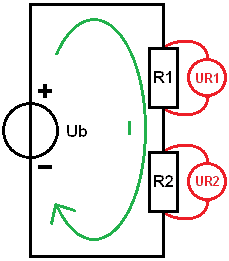
In the example, the loads (R1 and R2) are connected in series. The negative of R1 is connected to the positive of R2. The current through the resistors is the same. To use Ohm’s Law to calculate the current and ultimately the voltage drops, we can start by calculating the equivalent resistance. The resistance values are as follows:
- R1 = 15 A
- R2 = 10 A
To calculate the equivalent resistance, we replace resistors R1 and R2 with Rv in the diagram.
In a series circuit, we can add the resistance values together. The formula and calculation are shown below.
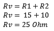

The outcome of the calculation shows us that the equivalent resistance amounts to 25 Ohms. In the subsequent examples, we can use the Rv to continue calculating.
Series Circuit: Calculating Current and Voltage Drops:
In this section, we calculate the total current and the voltage drops across resistors R1 and R2. For this, we first need a source voltage (Ub). In this calculation example, this voltage is 14 volts.
With a known source voltage (Ub) and equivalent resistance (Rv), we can calculate the total current (I). We determine I using Ohm’s Law:
The current in a series circuit is the same through each resistor. The green arrow in the image indicates the current direction. The current is 560 milliamps. A0
Now that the current is known, we can start calculating the voltage drops. This will determine how much voltage each resistor “uses”.
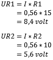
- The voltage (U) across resistor R1 is denoted as: UR1. Using Ohm’s Law, we multiply the current by the resistance value. The voltage across the resistor is 8.4 volts.
- UR2 is calculated with the same current but now using the resistance value of R2; this voltage is 5.6 volts.
As a check, you can add the voltage drops together and compare them to the source voltage. We add UR1 and UR2 together: this equals 14 volts, which is equal to the source voltage. If you arrive at a different answer, it may be due to a small rounding error or a calculation error.
Parallel Circuit: Calculating Equivalent Resistance:
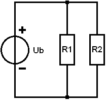
In this example, R1 and R2 are connected in parallel. Now the negative of one load is no longer connected to the positive of the other. The voltage across the resistors is now equal to the battery voltage. The current divides across the resistors. With equal resistance values, the total current (It, short for Itotal) divides by two. To calculate It, we must first determine the equivalent resistance. Again, we replace R1 and R2 with a single resistor called Rv. We then have the same situation as in the series circuit example. The resistance values are:
- R1 = 10 0A
- R2 = 20 50A
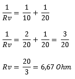
In a parallel circuit, we cannot add resistance values. The general formula is:
We substitute the resistance values of R1 and R2:
Method 1: We calculate the result of one-tenth and one-twentieth and add the values together. A0
Method 2: Another way is to calculate the equivalent resistance in fractional form. We again substitute the values of R1 and R2 into the equation. Under the division lines (the denominators), there are unequal numbers; we cannot add the denominators together. So we first equate them. In this example, it’s easy: one-tenth fits twice into one-twentieth, so we multiply one-tenth by 2. We then get two-twentieths. In proportion, that’s the same as one-tenth. With equal denominators, we can add the fraction: this results in three-twentieths. To calculate the equivalent resistance, we have to invert the fraction: 1/RV becomes RV/1 (we can then remove /1) and three-twentieths becomes 20 divided by 3. The result of 6.67 Ohms is equal to the result in method 1.
Parallel Circuit: Calculating Branch Currents:
We can calculate the total current (It) by dividing Ub by Rv:
The current Itotal will divide into I1 and I2. Through R1 flows a different current than through R2. At the junction, the branch currents come together again, and It flows back to the negative of the battery.
In a parallel circuit, the voltage across each load is equal to the source voltage:
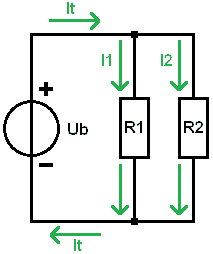
In the formulas for UR1 and UR2, we substitute the same value as the battery voltage: in this case, 14 volts. We divide the voltage by the resistance values and obtain the branch currents. Through resistor R1 flows a current of 1.4 Amps and through R2 700 milliamps.
When we add the two branch currents together, we get the total current of 2.1 Amps.
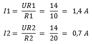
Combined Circuit:
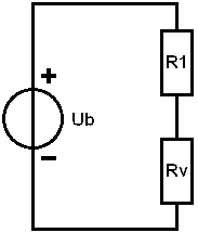
In a combined circuit, we have a series and parallel circuit in one circuit. In the image, we see that resistor R1 is in series with the parallel-connected resistors R2 and R3. In practice, we might find this in a poor positive wire to two bulbs: in that case, R1 is the transition resistance, and R2 and R3 are the bulbs.
We will calculate the currents and voltages based on the following data:
- Ub = 12 volts;
- R1 = 0.5 6B
- R2 = 15 6B
- R3 = 15 6B
In a parallel circuit, we know that the voltage across the resistors is equal to the source voltage. Since we now have a combined circuit, this is no longer true; a portion is taken up by R1. However, the voltages across R2 and R3 are equal to each other.
For clarification, we break down the calculations into 5 steps.
1. Determine Rv of the Parallel Circuit:
We replace R2 and R3 with Rv and calculate Rv in fractional form for convenience.
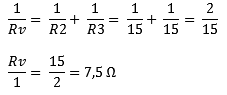
Now it is a series circuit: R1 remains of course 0.5 6B and Rv is now 7.5 6B
2. Determine Rv of the Series Circuit:
In step 1, the equivalent resistance of R2 and R3 was determined. The equivalent resistance was in series with resistor R1.
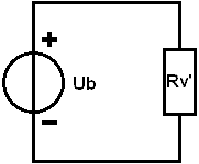
In this step, we add the resistance values of R1 and Rv to calculate the equivalent resistance once more, but now that of the series circuit. We call this equivalent resistance Rv’ (with an accent) because it is a “second” Rv in the circuit.
3. Calculate Itotal:
The total current amounts to 1.5 A and flows through resistor R1 and the equivalent resistance Rv’.
4. Calculate Voltage Drops:
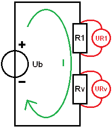
We stepwise reconstruct the diagram; we place R1 and Rv in series to calculate the voltage drops UR1 and URv using the total current and resistance values.
As a check: the added voltage drops match the source voltage: (UR1 + URv = Ub) so far no calculation errors have been made.
5. Calculate Currents:
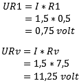
We finish the diagram. In step 4, we determined that the voltage across resistor R1 is 0.75 volts. The voltage across the equivalent resistance Rv is 11.25 volts. Because in a parallel circuit the voltage across the loads is equal, we know that the voltage across both R2 and R3 is 11.25 volts.
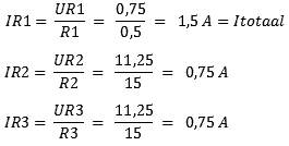
With the results of the calculations, it is seen that the total current flows through R1, and the current then divides across R2 and R3. With unequal resistance values, these currents differ from each other.
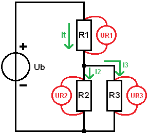
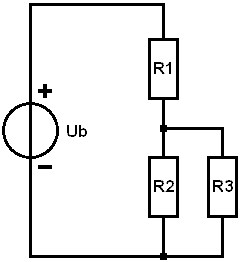
Combined Circuit Exercise:
In this section, you can practice calculating the combined circuit yourself. To make it easier for yourself, you can follow steps 1 to 5 from the previous paragraph. Extend the step-by-step plan with step 6 to calculate the voltage drops of R4 and R5.
Given:
- Ub = 10 volts
- R1 = 1 6B
- R2 = 10 6B
- R3 = 4 6B
- R4 = 5 6B
- R5 = 15 6B
Requested:
- All voltage drops (UR1 to UR5)
- All branch currents.