Topics:
- Assembling the MegaSquirt II ECU
- JimStim simulator
- TunerStudio
- Settings
Assembling the MegaSquirt II ECU:
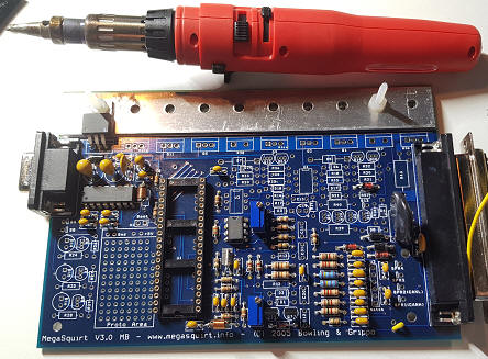
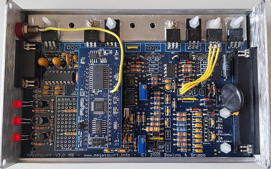
The MegaSquirt is delivered as a kit. The composition of the MegaSquirt depends on the engine configuration and the sensors and actuators used. Not all components can withstand high current levels. When choosing the ignition driver, it is also important to consider the type of coil being used. A choice must be made from three different options when assembling the MegaSquirt. In many cases, multiple circuits can be mounted, but the correct circuit is activated by means of jumpers.
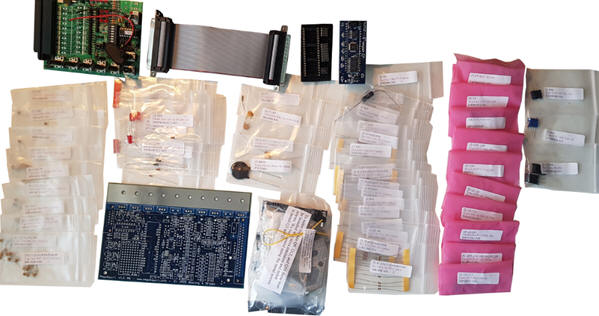
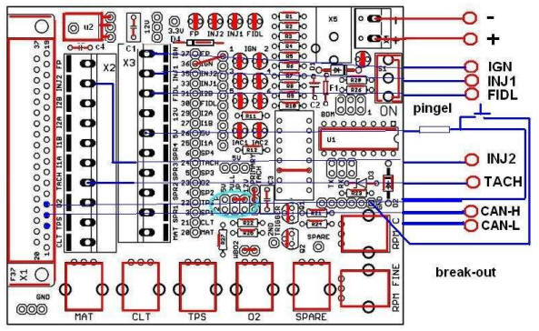
The image shows an overview of the supplied parts. The simulator is visible at the top left, which can be used to create and measure the input and output signals of the MegaSquirt after the assembly process. At the bottom center, the MegaSquirt circuit board is on the left and a bag with large connection components is on the right. The daughterboard, which makes it a MegaSquirt 2 version, is visible at the top center. This daughterboard is inserted into the mounted processor socket afterwards. Between the easily visible parts are fifty bags with loose components. Each bag contains different electrical components such as resistors, transistors, diodes, opamps, voltage regulators, LEDs, an opto-coupler, and several other ICs.
JimStim simulator:
The applied simulator is suitable for setting up the MegaSquirt before it is mounted on an engine. The simulator features a number of hardware circuits that can create sensor signals. Turning the potentiometers results in changing sensor values. On the computer screen, the gauges in the TunerStudio program will display the values (Appendix 29). The sensors that can be simulated are as follows:
- Intake air temperature;
- Coolant temperature;
- Throttle position;
- Lambda value;
- (Reserve);
- Crankshaft speed;
- Crankshaft speed (fine adjustment).
In addition to the sensor values, the adjustments of the engine management can also be checked. Adjusting one sensor value can affect the control of one or more actuators. On the connections, which serve as a breakout box, it is possible to measure the signals using a multimeter or oscilloscope.
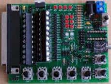
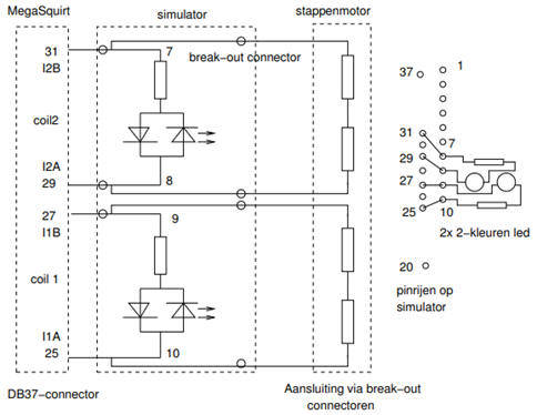
The image shows the assembled JimStim simulator where no controllers and jumpers have been applied yet. On the left side is the connector where a flat cable allows the connection between the MegaSquirt and the simulator. Once the assembly process is completed, the simulator is replaced by the connector on the engine to which all sensors and actuators are connected.
The simulator has a number of dip switches that properly set the crank signal. Appendix 17 provides a schematic overview. It is possible to choose between a 36-1 or a 60-2 crank reference wheel, between a 5-volt or 12-volt signal, and whether the crank position sensor provides an AC or DC signal. Naturally, the settings chosen correspond to the components applied on the engine. The simulator is equipped with several LEDs. These LEDs light up or blink when controlling the following electrical components:
- Fuel pump;
- Injector control 1;
- Injector control 2;
- Ignition control 1;
- Ignition control 2;
- PWM signal of the idle control valve (if present);
- Stepper motor control (if present).
The JimStim simulator is mounted on a panel with transparent plexiglass. Measurement connections are applied in the plexiglass. The connection between the simulator and the measurement connections should be made by soldering wires.
TunerStudio:
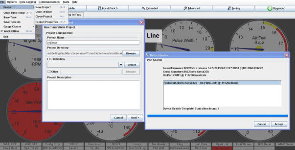
The MegaSquirt II ECU is connected to a desktop PC or laptop via the software program “TunerStudio”. Through this program, settings in the MegaSquirt can be loaded. The image below shows the screen where the MegaSquirt is connected to the PC via a COM port.
The image below shows the gauges of TunerStudio. While operating the potentiometers on the simulator, or while running the engine, the gauges in this screen indicate the sensor values and actuator controls.
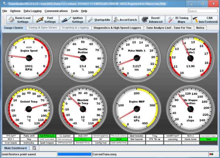
- Engine speed: Crankshaft speed
- Throttle Position: Throttle position, opening angle
- Pulse Width 1: Injector opening time
- Air:Fuel Ratio 1: Actual air/fuel ratio
- Coolant Temp: Coolant temperature
- Manifold Air Temp: Intake air temperature
- Engine MAP: Manifold absolute pressure
- Idle Stepper Position: Stepper motor position, number of steps
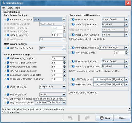
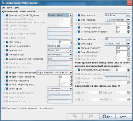
Engine settings in TunerStudio:
The engine properties are filled in the TunerStudio program. The images below show the screens where the settings have been made.
Next: Settings