Spring-loaded Check Valve:
A pressure relief valve protects the hydraulic circuit from excessive pressures. A pressure relief valve is also known as a pressure limiter valve or safety valve. Without this valve, pressure in the system could become too high, leading to leaks in seals or damage to components.
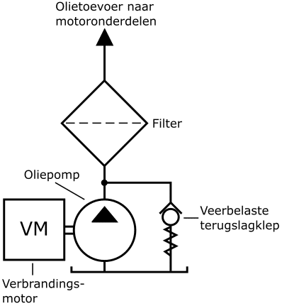
The simplest form is the spring-loaded check valve, as shown in the image below. For example, the oil pump with filter and safety system of a combustion engine is used. The oil pump is driven by the crankshaft. As soon as the oil pressure surpasses the spring force on the ball of the check valve, an opening forms, and the oil flows back to the reservoir. This type of pressure protection is found in lubrication systems where the maximum oil pressure must not exceed approximately 5 bar.
Besides the spring-loaded check valve, direct and indirect pressure relief valves are also common in hydraulics.
Direct-Acting, Spring-Loaded Pressure Relief Valve:
The direct-acting check valve is very similar to the above-mentioned spring-loaded check valve. However, the differences and advantages of the direct-acting pressure relief valve are:
- relatively simple and inexpensive construction;
- quick response to pressure surges and fluctuations in the system;
- seat valves ensure leak-free sealing.
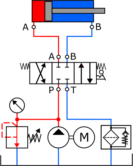
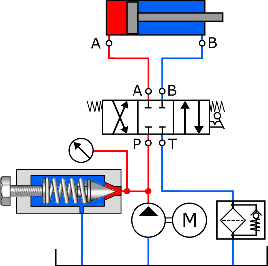
The two images below show the diagrams with a spring-loaded check valve with the symbol (left) and a drawing of the component (right).
The pressure relief valve is normally closed with a spring; no fluid passage is possible. In the diagram, we see the spring with an arrow: this indicates that the spring is manually adjustable. In the right image, we see the screw used to tension the spring. The more the screw is tightened, the higher the opening pressure becomes.
When the fluid pressure reaches the set pressure, it pushes the conical plunger against the spring force inward. An opening is created, allowing the fluid to flow directly to the return. The pressure on the pump side (the red line) does not continue to rise.
The disadvantage of the direct-acting pressure relief valve is that there is always internal leakage.
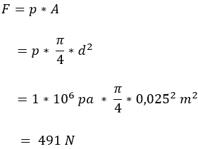
Calculating Required Spring Force for Pressure Relief Valve:
The following calculation illustrates the amount of spring force needed to keep the valve closed at a certain pressure. We use the following data:
- regulated pressure (p) = 10 bar (equivalent to 1,000,000 Pa);
- valve orifice = 25 mm.
The force the spring must deliver is considerable. At higher pressures, a heavy spring construction is required.
An alternative is an indirect pressure relief valve or a pilot-operated pressure relief valve.
Indirect Pressure Relief Valve:
In the previous section, it is shown that the spring force in a direct pressure relief valve must be as much as 491 N to keep the valve closed at a pressure of 10 bar.
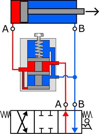
This makes the direct pressure relief valve unsuitable for hydraulic systems that operate at higher pressures (>100 bar) and large flow rates. To avoid heavy spring constructions, systems with high operating pressures use an indirect pressure relief valve. In the indirect pressure relief valve, fluid pressure is present on both sides of the main valve, allowing the spring to be smaller. The three diagrams below illustrate the schematic principle of this type of pressure control valve. The indirect pressure relief valve contains two valves, each closed at rest with its spring:
- pilot valve;
- main valve.
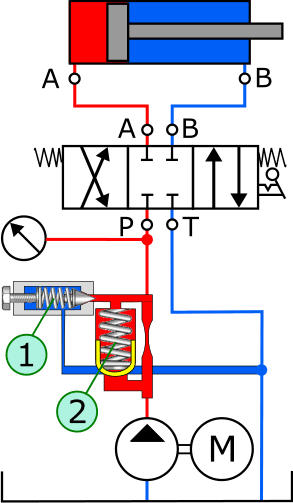
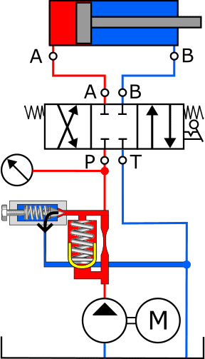
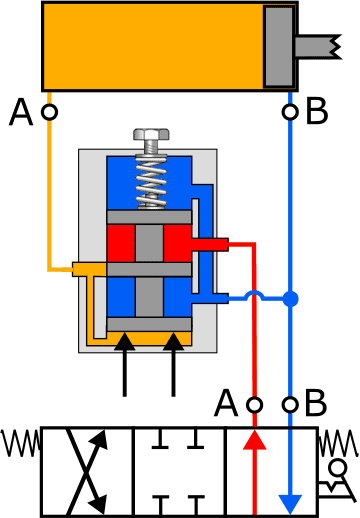
The system pressure from the hydraulic pump is directly connected at the bottom of the pressure control valve and reaches the pilot valve (1) via a restriction in the supply line and the main valve (2). As long as the system pressure does not exceed the pressure set by the pilot valve, both valves remain closed (image A). When the pressure becomes too high, for example when the cylinder has reached its end stop, the fluid pressure pushes the pilot valve (1) inward against the spring pressure (image B). The oil now flows through the restriction and the opened pilot valve, via the return channel to the reservoir.
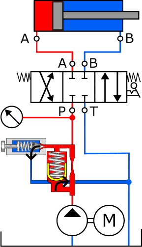
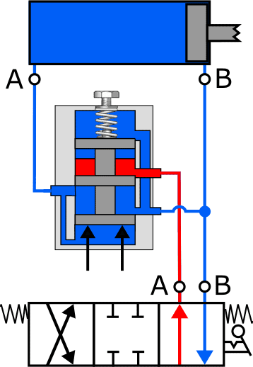
The restriction creates a pressure difference over the main valve even at a low flow rate. This pressure difference causes the main valve to open against the spring force (image C). In this way, the entire pump output can be discharged to the reservoir via the main valve.
Pressure Reducing Valve:
The pressure reducing valve aims to reduce the pressure in the hydraulic system or only in a part of the system to a desired value and keep it constant.
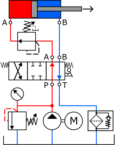
The following diagram shows the symbol of the pressure reducing valve in the pressure line between the control spool and the cylinder. The symbol somewhat resembles that of the pressure relief valve.
The pressure reducing valve allows the fluid pressure to pass as long as the pressure does not reach the set value. The cylinder can thus be controlled without problems.
Once the set pressure is reached, the pressure reducing valve closes the inlet and initially maintains the pressure constant. With a further increase in pressure on the cylinder side, the valve reduces this pressure by directing it to the return.
The following three diagrams illustrate the principle operation of the pressure reducing valve in three situations. For convenience, only part of the diagram is shown: the hydraulic pump, pressure relief valve, etc. are omitted due to size. Also, the piston rod in figures B and C is shortened due to image size.
- A. The pressure reducing valve is at rest. The fluid from the hydraulic pump flows unabated to connection A of the cylinder;
- B. The piston in the cylinder has reached its end stop. The pressure in the supply line increases. The control plunger in the pressure reducing valve closes the supply from the control spool to the cylinder. The pressure in the cylinder is held constant (yellow);
- C. When the load at the end of the piston rod increases, this will affect the fluid pressure in the cylinder. The control plunger moves further upward due to the pressure increase at the bottom side. This opens the return channel, allowing the fluid from the cylinder to flow to the reservoir.
After the fluid pressure drops, the process reverses: with a pressure drop, the plunger closes the return channel and maintains the pressure constant, after which the plunger moves further down and a pressure increase occurs again. The pressure that the pressure reducing valve must work with can be adjusted manually by turning the screw further in or out.
Sequence Valve:
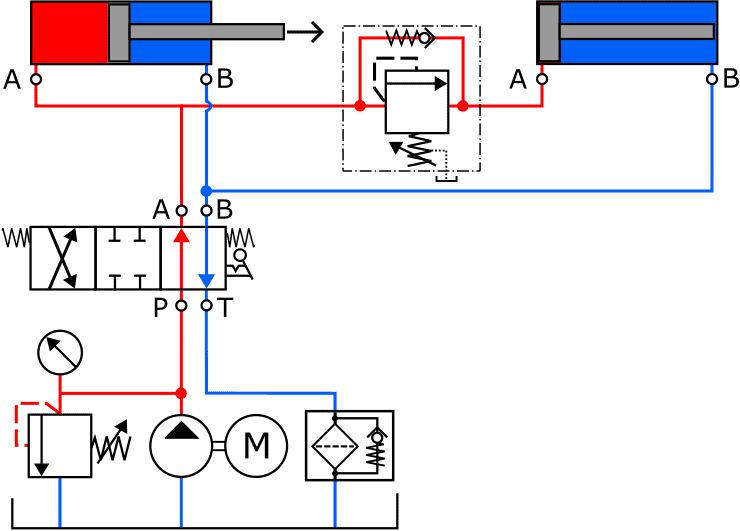
A sequence valve can be used to control, for example, two cylinders in a constructor’s desired sequence. The actuation sequence cannot be regulated during operation; the least loaded cylinder will move first.
In the image below, the left cylinder will be extended first. Once it has reached its end stop, the pressure in the red supply line increases. The sequence valve opens at a certain preset pressure. Once the spring force in the sequence valve is overcome, the fluid flows to the right cylinder, which will then start moving. A sequence valve is essentially a pressure relief valve with a built-in check valve. The check valve opens when the control spool switches the supply to connection B of the cylinder and the return to A.
Related page: