Subjects:
- Spring loaded check valve
- Direct Acting, Spring Loaded Pressure Relief Valve
- Calculating required spring force pressure relief valve
- Indirect pressure relief valve
- Reducing valve
- Sequence valve
Spring loaded check valve:
A pressure relief valve protects the hydraulic circuit against excessive pressures. A pressure relief valve is also called a pressure limiting valve or safety valve. Without this valve, the pressure in the system could rise too high, causing seals to leak or components to fail.
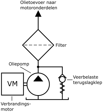
The simplest embodiment is the spring-loaded check valve, which can be seen in the following figure. As an example, the oil pump with filter and protection system of an internal combustion engine is used. The oil pump is driven by the crankshaft. As soon as the oil pressure overcomes the spring pressure on the check valve ball, an opening is created and the oil flows back to the reservoir. We find this type of pressure protection in lubrication systems where the maximum oil pressure may not exceed approximately 5 bar.
In addition to the spring-loaded non-return valve, we often come across direct and indirect pressure relief valves in hydraulics.
Direct-acting, spring-loaded pressure relief valve:
The direct acting check valve is very similar to the spring loaded check valve located above. However, the differences and advantages of the direct acting pressure relief valve are:
- a relatively simple and inexpensive construction;
- quick response to pressure surges and fluctuations in the system;
- seat valves seal leak-free.
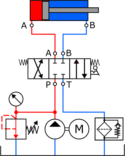
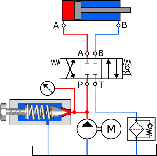
The two pictures below show the schematics showing a spring loaded check valve with the symbol (left) and a drawing of the component (right).
The pressure relief valve is spring closed as standard; no passage of liquid is possible. In the diagram we see the spring with an arrow in it: this means that the spring is manually adjustable. In the picture on the right we see the screw with which the spring can be tensioned. The further the screw is screwed in, the greater the opening pressure becomes.
When the fluid pressure has reached the set pressure, it pushes the conical plunger inwards against the spring force. An opening is created through which the liquid can flow directly to the return. The pressure on the pump side (the red line) does not increase any further.
The disadvantage of the direct acting pressure relief valve is that there is always internal leakage.
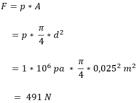
Calculating required pressure relief valve spring force:
The following calculation provides insight into how much spring force is required to keep the valve closed at a certain pressure. We use the following data:
- pressure to be regulated (p) = 10 bar (equals 1.000.000 Pa);
- valve diameter = 25 mm.
The force that the spring has to deliver is quite high. At higher pressures, a heavy spring construction is required.
An alternative is an indirect pressure relief valve or a pilot operated pressure relief valve.
Indirect pressure relief valve:
The previous section shows that the spring force with a direct pressure relief valve must be no less than 491 N to keep the valve closed at a pressure of 10 bar.
This makes the direct pressure relief valve unsuitable for hydraulic systems that work with higher pressures (>100 bar) and a large volume flow. To avoid heavy spring structures, systems with high working pressures use an indirect pressure relief valve. In the indirect pressure relief valve, a liquid pressure prevails on both sides of the main valve, so that the spring can be made smaller. The three pictures below show the schematic principle of this type of pressure control valve. The indirect pressure relief valve contains two valves that are each closed in rest position with its own spring:
- pilot valve;
- main valve.
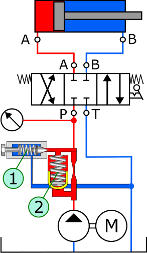
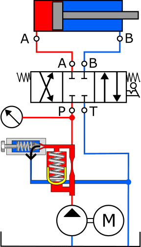
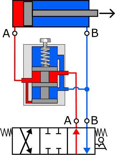
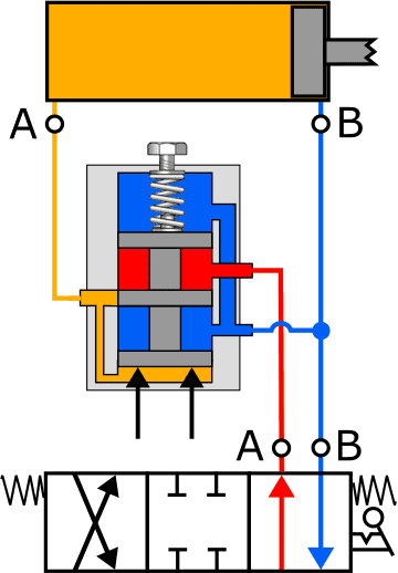
The system pressure from the hydropump is connected directly below the pressure control valve and reaches the pilot valve (1) through a throttling in the supply line and the main valve (2). As long as the system pressure does not exceed the pressure set with the pilot valve, both valves remain closed (Figure A). When the pressure rises too high, for example when the cylinder has reached its end stop, the fluid pressure pushes the control valve (1) inwards against the spring pressure (Figure B). The oil now runs via the throttle and the open control valve, via the return channel to the reservoir.
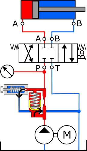
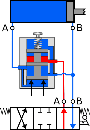
The throttling already causes a pressure difference across the main valve from a low volume flow. This pressure difference causes the main valve to open against the spring force (Figure C). In this way the entire pump output can be discharged to the reservoir via the main valve.
Reducing valve:
The function of the pressure reducing valve is to reduce the pressure in the hydraulic system or only in part of the system to a desired value and to keep it constant.
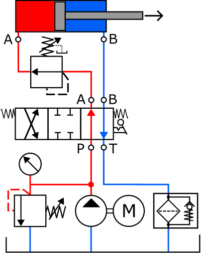
The following diagram shows the reduction valve symbol in the pressure line between the control valve and the cylinder. The symbol is somewhat similar to that of the pressure relief valve.
The pressure reducing valve allows the fluid pressure to pass as long as the pressure does not reach the set value. The cylinder can thus be controlled without any problems.
When the set pressure is reached, the pressure reducing valve shuts off the supply and initially keeps the pressure constant. With a further increasing pressure on the cylinder side, the valve reduces (reduces) this pressure by discharging it to the return.
The three diagrams below show the principle operation of the pressure reducing valve in three situations. For convenience only part of the diagram is shown: the hydraulic pump, pressure relief valve, etc. are omitted due to the size. Also, the piston rod has been shortened in Figs. B and C due to the image size.
- A. The regulator is at rest. The liquid from the hydropump continues to flow unabated to connection A of the cylinder;
- B. The piston in the cylinder has reached the limit stop. The pressure in the supply line increases. The control plunger in the reducing valve closes the supply from the control slide to the cylinder. The pressure in the cylinder is kept constant (yellow);
- C. As the load on the end of the piston rod increases, it will affect the fluid pressure in the cylinder. The control plunger moves even further upwards due to the pressure increase at the bottom. This opens the return channel and allows the liquid to flow from the cylinder to the reservoir.
After the liquid pressure has dropped, the process takes place backwards: when the pressure decreases, the plunger closes the return channel and keeps the pressure constant, after which the plunger moves further downwards and a pressure increase takes place again. The pressure at which the pressure reducing valve should operate can be adjusted manually by turning the screw further in or out.
Sequence valve:
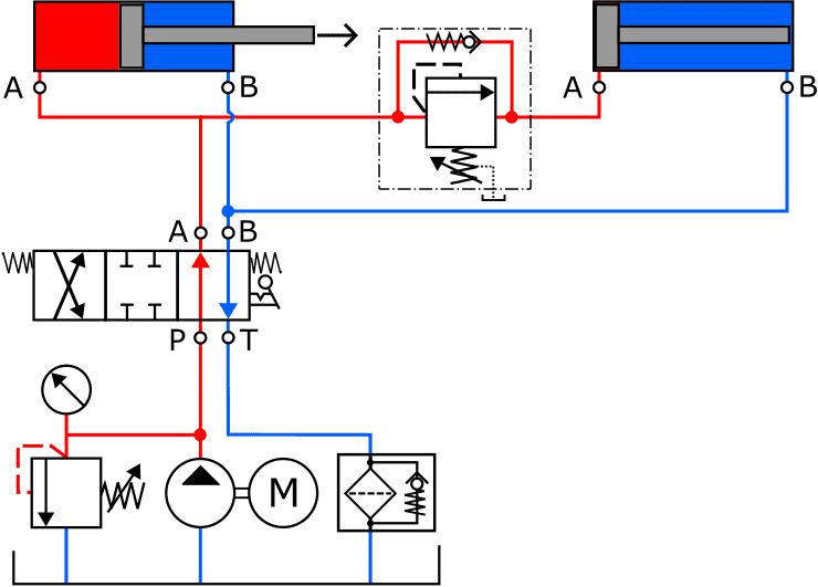
With a sequence valve, it is possible to control, for example, two cylinders in a sequence desired by the manufacturer. The order of submission cannot be controlled during operation; the least loaded cylinder will move first.
In the image below, the left cylinder will be sent out first. As soon as it has reached its limit stop, the pressure in the red supply line increases. The sequence valve opens at a certain preset pressure. Once the spring force in the sequence valve has been overcome, the fluid flows to the right-hand cylinder where it will be set in motion. A sequence valve is basically a pressure relief valve with a built-in check valve. The non-return valve opens the moment the control slide switches the supply to connection B of the cylinder and the return to A.
Related page: