Introduction to OBD:
OBD stands for On Board Diagnostics. OBD has both a regulatory and diagnostic function, particularly in the engine management system of the ECU. The OBD system can detect a fault by reading it using a diagnostic tester. The fault code can be looked up in the OBD Fault Code List (if the code is not brand-specific).
TIP: Also visit the website GerritSpeek.nl, where you can find extensive information about the possibilities with the VCDS program and in-depth information about fault codes.
OBD 1:
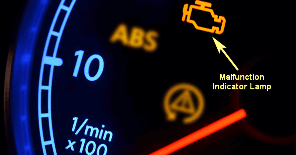
This is the first OBD system developed by GM (General Motors). It was introduced in 1980 and first used in the US in 1988. The primary goal of this system was to reduce emissions. The system was designed to detect defects and deviations independently, thereby limiting harmful emissions. When a defect or deviation was detected, the MIL (Malfunction Indicator Lamp) would light up, which needed to be read by an automotive technician. The driver was notified by the MIL to have the issue resolved as quickly as possible.
All vehicles produced from 1991 were required to be equipped with OBD1. The first versions from brands like Opel and Volvo used a blink code. Other brands developed their own connector with their own fault codes. OBD 1 had no guidelines, unlike OBD II.
Blink Code:
In the first generation of OBD1, the mechanic must read the blink code to determine the fault code. Often, an action must be taken to start the blinking sequence; this action involves:
- Connecting two separate connectors in the engine compartment or interior;
- Bridging two terminals in a connector, again in the engine compartment or interior.
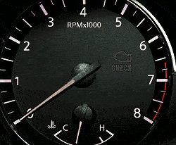
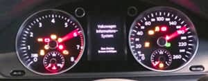
A blink code consists of two or three numbers. In the following image, the check light blinks: 4x blink – short pause – 5x blink – long pause. This indicates fault code 45, which stands for: lambda sensor – rich mixture detected.
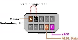
Opel:
This type of diagnostic connector is usually built into the engine compartment. Bridging two terminals in this connector will cause the check light in the instrument panel to start blinking.
- Bridge A-B: codes for the engine management system;
- A-C: automatic transmission;
- A-H: alarm system;
- A-K: ABS
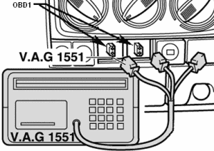
Volkswagen:
Volkswagen has 2 separate connectors for OBD1. The diagnostic tool (in this case the VAG 1551) can be connected to these 2 connectors. By selecting the correct channel on the diagnostic tool (01 for engine electronics), the fault memory can be read and cleared in the service menu.
BMW:
At BMW, the OBD1 connector is round. This connector is connected to the diagnostic equipment using a cable. The faults are displayed with descriptions on the diagnostic tester’s screen and can also be cleared.
OBD II and EOBD:
OBD II was introduced in 1996. Since 2004, OBD has been mandatory in Europe. In the US, it continues to be called OBD II, while the European variant is called EOBD. They are identical except for a few minor adjustments; EOBD does not require EVAP control (evaporation of harmful fuel vapors), whereas it is mandatory in the US. Cars from 2008 onwards must have OBD II and EOBD with CAN bus communication. Click here for more information on the CAN bus.
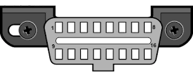
Various aspects were standardized; such as the type and placement of the 16-pin OBD connector (Data Link Connector, abbreviated as DLC), the fault code structure, and the communication protocols. Emission-related fault codes must be readable by anyone.
EOBD is mandatory for the drivetrain of all vehicles and is independent of brand-specific diagnostics. The EOBD, through the engine management system, constantly monitors all systems (such as the lambda sensor) and signals when the actual emissions are one and a half times the emission standard. The MIL will not light up immediately, but the system will store the fault. When a second trip is made under the same conditions and the emissions are again one and a half times as high as the maximum specified, the MIL will light up. The driver is then notified that there is a fault in the engine management.
When the car is read with a diagnostic tool, a fault code appears on the device. This code is also referred to in technical terms as a DTC (Diagnostic Trouble Code). A DTC can be, for example, a P-code. This code has a meaning; Click here to go to the OBD fault code list.
Reading and Clearing the Fault Memory:
The vehicle can be read with a diagnostic tool. This needs to be connected to the OBD2 port in the vehicle’s interior. The diagnostic tool then connects to various components, including the gateway. This OBD2 port is usually located near the driver’s seat, typically under the dashboard or in the center console.
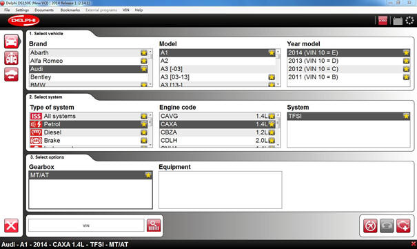
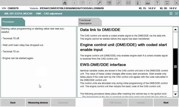
A special OBD2 cable must be connected to the connector port. This cable should be connected to a diagnostic device. Once the laptop is connected to the reader head and the cable, the diagnostic program can be started. First, some vehicle data must be entered, as shown in the image below:
After connecting, you are asked what you wish to do next. One of the options is to read a fault code. A fault code is also called a Diagnostic Trouble Code (DTC). A DTC consists of a letter followed by four numbers.
- The letter P stands for Powertrain; which includes the engine and transmission.
- B stands for Body; which includes airbags, seat belts, heating, and lighting.
- C stands for Chassis; which includes the ABS and ESP systems.
- U stands for Network; pertaining to CAN bus communication.
The four numbers indicate what it concerns. Extensive lists of codes and their meanings can be found online.
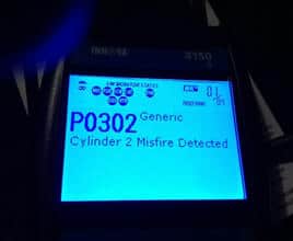
As an example, let’s discuss a car that idles irregularly. The engine management light is on.
This light is also known as the Malfunction Indication Lamp (MIL). When this light is on or has been on, it is certain that a fault is stored in the fault memory. It is then time to read the car.
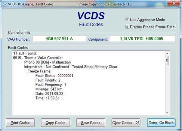
On the tester screen shown in the image, the fault code P0302 appears. This code indicates that an incomplete combustion was registered at cylinder 2. This could have occurred once, multiple times, or could be a permanent issue. Fault code P0301 arises when there is an incomplete combustion detected at cylinder 1, and fault code P0303 at cylinder 3, etc.
When a sensor provides a value that falls outside the tolerances, the ECU determines which fault code it corresponds to and stores it in memory. The diagnostic equipment also provides text; the software recognizes the code (e.g., P0302) and associates it with a text (Cylinder 2 Misfire Detected). This is all pre-programmed in the diagnostic software.
Each brand also has brand-specific codes; for this reason, it is often necessary to select the brand, type, year of manufacture, engine code, and fuel system at the beginning. If the wrong brand is selected, an incorrect text may be attached to the fault code. Brand-specific testers or very comprehensive diagnostic equipment also have diagnostic programs in the software. When a fault code is clicked, a test program will open that can be walked through step by step. At the end of the test, the software will come to a conclusion or indicate a specific direction where the technician should measure.
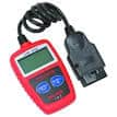
Besides laptops with comprehensive diagnostic programs, there are also simple hand readers available. These readers can often read emissions-related faults, such as various engine faults. However, faults in the chassis or airbags can often not be read with these.
Fault codes can indicate that a part is broken. But a technician cannot simply assume that a fault with, for example, a sensor, means that the sensor is defective. It could just as well be the wiring or connector that is corroding, causing a transition resistance. However, the fault code often gives a good indication of where the cause of the issue can be located. As an example, let’s revisit fault code P0302, where misfire on cylinder 2 is recognized. The combustion in this cylinder was not good. This can have, for example, the following causes:
- Poor ignition (defective spark plug, ignition coil, or ignition cable)
- Poor injection (defective or dirty injector)
- Compression loss (poor sealing of the intake or exhaust valves, defects in the cylinder head or piston)
With only the fault code P0302, it’s easy to find which cylinder the issue is occurring on, but that’s when the real work begins. By swapping parts like the spark plug, coil, or injector, it can be checked if the fault moves. The coil from cylinder 2 can be swapped with that of cylinder 4. If the fault is cleared, the engine is restarted, and the fault memory is read again, it can be determined if the fault has moved. If the fault code P0304 now appears, it means that a poor combustion is now detected at cylinder 4.
The cause is found; the coil is defective and needs to be replaced. The coil generates a voltage of up to 30,000 volts needed for the spark plug to create a spark. If the fault is still present after swapping the coil, the spark plug and injector can also be swapped and checked in the same way. After the repair, faults should always be cleared.
Faults recorded in the fault memory are not always active at the time of reading. They can be faults that occurred once or multiple times in the past. Sometimes these faults can be ignored as they might be caused, for example, by a low battery voltage, but if the customer has a complaint that the car sometimes stutters, sometimes starts poorly, or sometimes hesitates, attention should be given to them. An example of a currently present fault can be seen in the image.
The fault is present on the Throttle Valve Controller. This is a translation of the “throttle body”. The fault code is P1545 and it states intermittent. This is English for “sporadically occurred.” It also mentions Fault Frequency: 1, meaning the fault occurred only once. The mileage and the date when the fault occurred are also shown.
If a connection is made with the customer’s complaint, further investigation into the cause of the fault should be performed. If the fault were cleared, it’s likely to stay away, especially if the fault occurred only once. But there is also a chance the fault may reoccur soon. Therefore, the customer cannot simply be sent away after clearing the fault. Clearing does not solve the problem.
Instead of Intermittent, the memory might also state static. In this case, the fault is currently present and cannot be cleared.
If an attempt is made to clear the fault, it will almost certainly return immediately.
Actuator Control:
Another method to locate faults with diagnostic equipment is to control actuators.
Actuators are all components that can be controlled; think of a window motor, which is controlled by operating a switch.
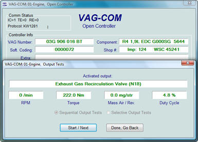
Or an EGR valve in the engine; controlled by the ECU to recirculate exhaust gases. With diagnostic equipment, these actuators can be controlled manually.
To check the movement of the EGR valve, one does not necessarily have to start the engine and wait for the ECU to operate the valve itself. By using the diagnostic equipment, the valve can be controlled when the technician sees fit.
An actuator diagnosis can also be useful when, for example, the trunk lid does not open with the trunk lid switch. By using diagnostic equipment to control the trunk lid motor, the trunk opens. If this does not happen when the trunk lid switch is used, one can search the value of the switch in the live data.
If the value in the live data remains at 0 (which means off) instead of 1 (which would appear during operation), it can be concluded that the switch is defective. The trunk lid is, after all, operable with the diagnostic equipment.
An actuator test can also be performed on the instrument panel. During the test, all indicator lights are turned on, all pixels on the maxidot-display are activated, and all gauges move to the maximum. Any issues, such as a fuel gauge that doesn’t move beyond halfway, will be immediately noticeable.
Coding, Initializing, Learning:
After replacing components such as control units, they often need to be coded before they can be used.
The coding consists of numerous hexadecimal numbers and letters. This is shown in the image below:
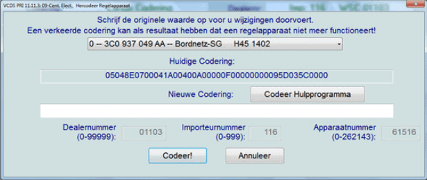
In this case, the Central Electronics control unit is replaced. If a new control unit is ordered, the software is preinstalled, but the options of the car must still be made known. There’s a difference between a base model without air conditioning, etc., and a fully-equipped car with air conditioning, seat heating, power windows, etc.
The coding is structured as follows:
05048E0700041A00400A00000F00000000095D035C000
The meanings could be as follows:
First number: 0= left-hand drive car, 1= right-hand drive car.
Second number: 1= Australia, 2= Asia, 3= South America, 4= Europe, 5= North America.
Third number: 0= Miles per hour, 1= Kilometers per hour.
The first three numbers indicate it is a left-hand drive American car displaying Miles per hour. Apparently, this is pre-programmed as standard during production. Each control unit receives the standard coding. After installation, the control unit must be recoded:
- The second number (the 5) must be manually changed to a 4 (from North America to Europe).
- The third number (the 0) can be manually changed to a 1.
In the car, the NL language will be set, and kilometers will be displayed instead of Miles. Each number or letter in the sequence has its own meaning.
The initializing is done differently. Often a simple push of a button is enough to initialize an electronic component in the car.
Components that need to be initialized include:
- The throttle body, after cleaning or replacement. The ECU must read the throttle position sensor values (potentiometers) at fully closed and fully open positions during learning, so all intermediate values can be determined. If the throttle body is not initialized/learned, the ECU cannot rotate the throttle properly. The consequence is that the engine gets too much or too little air idling, causing it to run poorly at idle. During Basic settings, “ADP is running” will be displayed, followed by “ADP OK.” During “running,” the throttle is set in multiple positions and the signal voltage of the potentiometers is checked. At “ADP OK,” the adjustment is successful.
- The rain sensor after windshield replacement. If not properly learned, the rain sensor may activate the wipers too early or too late when raindrops fall.
- The steering angle sensor after mounting work on the steering column;
- The tire pressure after the tires have been inflated or replaced;
- Vehicle height after suspension components have been replaced.
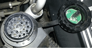
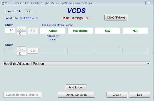
- Headlight height after replacing a headlight (see image below).
What happens during initialization is that the stored values are erased and replaced with new (actual) values.
If no corrective action is taken regarding the initialization of the steering angle sensor after repair work on the steering column, the steering angle sensor may think that the steering wheel is always slightly turned even when driving straight ahead. This is detrimental to systems like the ESP. By placing the steering wheel exactly in the straight-ahead position and commanding the diagnostic device to initialize the steering angle sensor, the car’s computer knows the exact point when the steering wheel is straight ahead. Learning, for example, applies to keys. When a new key is acquired, the car cannot immediately start. First, the key code must be registered in the car. This often happens with diagnostics. The key code is stored in the car’s control unit. Only when the key code is recognized by the control unit is the immobilizer disabled, allowing the car to start.
Readiness Test:
The readiness test is a self-check of the EOBD system. While driving, EOBD constantly checks the emissions-related controls. The driving cycle must consist of; a cold start, an urban drive, and a highway section. Several decelerations to 0 km/h followed by accelerations must also occur. After this driving cycle, the readiness test can end as “okay” or “not okay.” The readiness test is continuously executed by the engine management system.
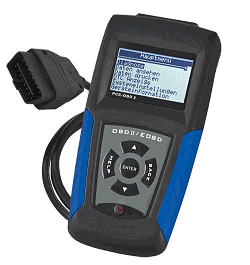
During the MOT, it is mandatory to read the EOBD to check the status of the readiness test and the presence of fault codes. This is allowed with a simple hand tester like the one shown in the image to the right. This does not need to be brand-specific and is only tasked with displaying the emissions-related fault codes and the readiness test.
During the readiness test, the following are checked:
- EGR function
- Lambda Sensor (operation, aging, heating)
- Fuel Trims (LTFT)
- Catalytic Converter
- Fuel System
- Secondary Air System
- Exhaust Gas Sensor (diesel)
- Particulate Filter (diesel)
If, for example, a cylinder combustion is not correct, or the catalytic converter is malfunctioning (this is checked with the second lambda sensor, the switching sensor), the readiness test is stored as “not okay.” A fault code is stored in the fault memory, which can be read with a simple hand tester or other advanced reading equipment.
When these faults are cleared, the readiness test is also cleared. Thus, it can take some time before the erased faults return (if not resolved by the repair). So it’s possible for the fault to stay away for a while after clearing and later return. Once the readiness test is complete (after the driving cycle), the fault may reappear. After clearing the faults, the readiness test will show “not okay” in the hand tester. It will take between 10 and 40 km before the new readiness test is stored again.
This also prevents emissions-related faults from being quickly cleared before the MOT is registered. The fault code may have disappeared, but the inspection controller will see that the readiness test is not okay.
Standardization in Communication Between the Diagnostic Tester and the Car:
With OBD II and EOBD, the communication between the diagnostic tester and the car is standardized. A fixed number of service modes are adhered to. These service modes each have their own function. Since it’s quite extensive, a table with general information is provided first. Below that, a detailed explanation follows…
The table of different service modes:
| Service 01 | Real-time Data: |