Introduction:
In automotive technology, measuring instruments are frequently used, for example, during an engine inspection. Measurement tools are also used for tasks such as measuring the thickness of the brake pads or the brake disc. To perform a measurement, it is important to know the precision with which the tool is made. With the internal jaws of a caliper, the cylinder diameter can be measured, but it is not precise enough (1/20 mm). A dial indicator is much more accurate (1/100 mm).
The most common measuring tools in the workshop and their precision are:
- Caliper (0.05 mm, which is the same as 1/20 mm)
- Micrometer (0.01 mm, or 1/100 mm)
- Dial Indicator (0.01 mm)
- Feeler Gauge (0.05 mm)
- Plastigage (accuracy depends on the type).
This page explains how to set, read, and possibly calibrate the aforementioned measuring tools and provides examples of measurements.
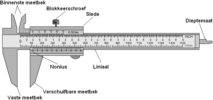
Caliper:
The caliper is a commonly used measuring tool in automotive technology. With the caliper, the inner, outer, and depth dimensions of a component can be measured accurately to the twentieth of a millimeter.
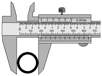
Measuring with the fixed jaw:
By clamping the component in the fixed jaw, the size can be read. You can now read 20 mm on the rule. This is the outer diameter of the ring.
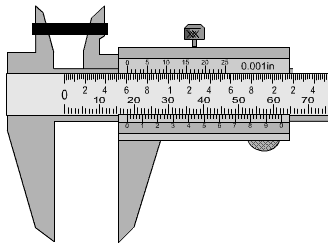
Measuring with the inside jaws:
By clamping the jaws inside the ring, the inner diameter can be read. This is 18 mm. That means the ring is (20-18) = 2 mm thick.
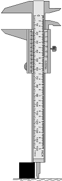
Measuring with the depth gauge:
For instance, for objects that cannot be removed from the surface or cylinders with a bottom, the height can be measured using the depth gauge. Place the end of the depth gauge on the surface and the thicker part of the caliper on the component to determine the height. In this case, the height of the black block is determined:
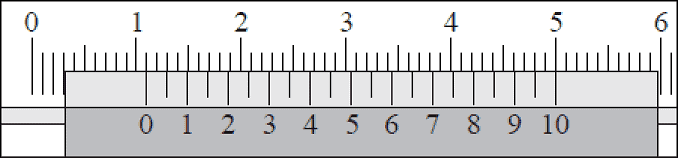
To read the caliper, you must also look at the tenth of millimeters. The place where the next line of the vernier scale exactly aligns with the line of the ruler indicates the measurement in tenths of millimeters (the number after the decimal point). In the image, the 0 of the vernier scale is at 1.1 cm, so 11 mm on the ruler. The line of the number 10 on the vernier scale also aligns with the line on the ruler. This means that exactly 11.0 mm is measured.
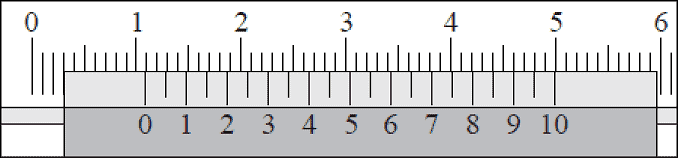
In the next measurement, the vernier is slightly shifted to the left, and we have a number after the decimal point. We look at where the next line of the vernier scale aligns exactly with the line of the ruler. In the image, the 0 of the vernier is at 1.1 cm, so 11 whole millimeters. The line of the number 9 on the vernier scale also aligns with the line of the ruler. This means that exactly 10.9 mm is measured.
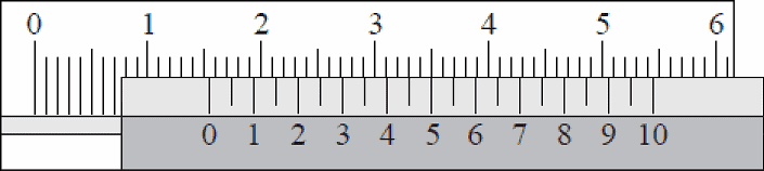
The measurement in the image follows the same principle. In this case, the 0 of the vernier is halfway between 15 and 16 mm on the ruler. You can already deduce that the decimal number will be around 4, 5, or 6. The lines of the ruler and vernier align at 5; therefore, 15+0.5 = 15.5 mm is now measured.
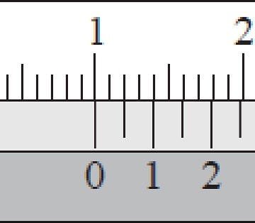
There are also small lines between the numbers on the vernier. These indicate the five hundredths of a millimeter. The line between 0 and 1 on the vernier aligns with the line on the ruler. In the image, (10 + 0.05) = 10.05 mm is measured. Reading a five hundredth requires a trained eye.
In this animation, reading the vernier is clarified with red arrows.
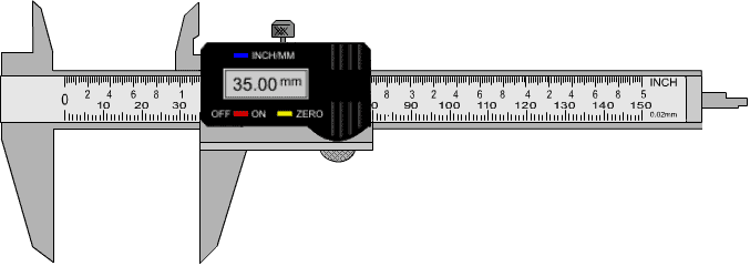
A caliper can also be digital as seen in the image. The dimensions of the component being measured can be read on the digital display. It can often be set to both inches and millimeters.
There are also calipers with an analog dial gauge at the place where the digital display is found in the image above. This type of caliper is not used much, but it depends on what the user prefers to use.
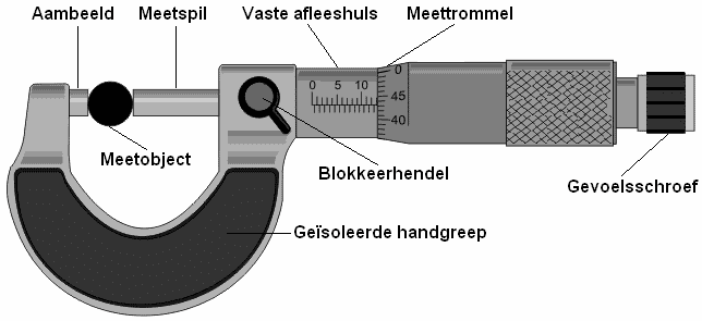
Micrometer:
The micrometer (also known as a micrometer caliper or micrometer screw gauge) can be used to measure components up to 25 mm in size with a precision of one-hundredth of a millimeter (0.01 mm). With one revolution of the measuring drum, the spindle moves 0.5 mm.
The micrometer must always be held by the insulated handle, as the heat from the hands can affect the measurement result. Local heating in the micrometer can cause the material to expand slightly. Especially for a measurement that must be accurate to a hundredth, it is important to follow the instructions.
The component to be measured should be placed between the anvil and the spindle. By turning the measuring drum, the spindle moves back and forth. Before the spindle touches the component, the last distance must be adjusted with the feeler screw. The feeler screw has a click mechanism that produces a ‘clicking’ sound at a certain exerted force. When you hear this, you know you shouldn’t tighten the meter further. Over-tightening the micrometer can yield incorrect measurement results. The measuring drum can be locked with the locking lever to prevent further turning.
Below is an image of a micrometer measuring the size of a ball bearing (the measured object).
In the image above, the ball bearing is 13.43 mm thick. On the top scale, you see 10, with three additional lines. Each line is a millimeter, so 10+3=13 mm. The number after the decimal point is read on the measuring drum. Here, the numbers 40 and 45 are shown. If you look closely, you see that the line of the scale aligns with 43. Together, this makes 13.43 mm.
The measuring drum has a scale from 0.0 to 0.49 mm. This is because the scale with the whole millimeters (to the left of the measuring drum) also contains half millimeters; the bottom lines indicate the half millimeters. Below are some examples.
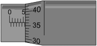
The horizontal line shows the whole millimeters. In this case, that is 13 mm. The line of 16 mm on the measuring drum aligns with the horizontal line on the reading sleeve. The measurement indicated by this image is (13 + 0.16) = 13.16 mm.
In the image, the line below the scale of the reading sleeve is visible. This line under the horizontal line indicates that it is a half millimeter. According to the scale, it is at least 5.5 millimeters (without considering the measuring drum). The scale on the measuring drum indicates 36. The measurement currently indicated is (5.5 + 0.36) = 5.86 mm.
In this image, the line at the bottom of the scale again is closest to the measuring drum. Therefore, according to the horizontal scale, it is at least 12.5 mm. Then we add the indicated value from the measuring drum, which is 0.35 mm. Finally, we sum 12.5 and 0.35.
This makes (12.5 + 0.35) = 12.85 mm in total.
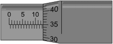
In this image, the indicated measurement is (16 + 0.355) = 16.355 mm.

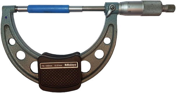
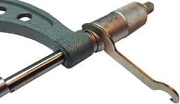
The image shows the micrometer indicating a value of 75.235 mm. The scale on the measuring drum is between 23 and 24 mm. Since the gauge is 75 mm, the micrometer deviates by 0.235 mm. Every measurement performed will therefore be too high. With a special adjustment fork, the sleeveless should be rotated relative to the handle. The adjustment fork is visible in the image above.
Before using the micrometer, it must first be calibrated. Incorrect calibration leads to measurement errors! The calibration of the micrometer is done with a special gauge. The gauge in the image below is exactly 75.00 mm. This means when the micrometer measures the gauge, it should indicate this exact number. If there is a wrong measurement, we must first calibrate the micrometer by turning the inner drum with the fork.
Dial Indicator:
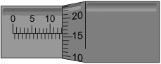
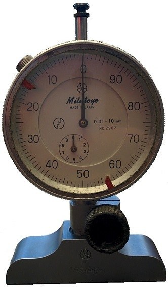
With the dial indicator, a very precise depth measurement can be performed. The small hand on the inside indicates the whole millimeters, and the large hand indicates the number after the decimal point. When the dial indicator is placed on a flat surface, it should read 0.00 mm, as seen in the image below. The outer ring can be turned to allow calibration. If 0.3 mm is read when it is on a flat surface, the outer ring should be turned so that the large hand indicates 0.
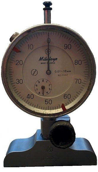
The dial indicator in the image shows 5.00 mm. The small hand is on 5, and the large hand is on 0. If the large hand were on 81 and the small between 5 and 6, the meter would read 5.81 mm. The further the probe on the underside is pushed up, the smaller the read value will be.
The dial on the micrometer reads: 0.01 – 10 mm. This means the micrometer can show a value between 0.01 and 10 mm. A depth measurement cannot be performed where the depth is 12 mm because the probe is too short, and the hands cannot indicate that. To measure values greater than 10 mm, various extensions are supplied with the micrometer. An example is seen in the image. The extension is measured with a micrometer here. It shows a value of 10.0 mm.
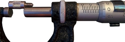
Only the barrel-shaped part is measured, not the thread. By attaching this extension to the micrometer, the probe is no longer too short. A value of, for example, 12 mm can now still be measured. It is necessary to pay attention to the fact that the length of the extension is added to the measured value. Here’s an example: if the micrometer indicates a value of 5.19 mm, the actual size is then the measured value + the length of the probe, so 5.19 + 10.00 = 15.19 mm.
On these pages, measurements with the dial indicator are performed:
Feeler Gauge:
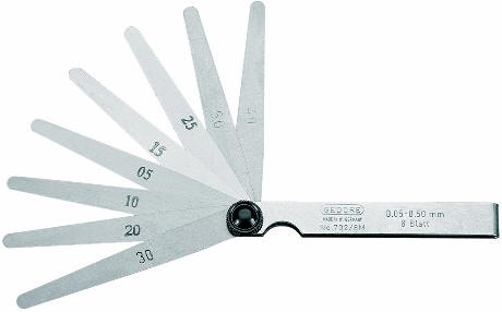
The feeler gauge is used to measure the gap between two parts. The feeler gauge consists of a number of metal strips, each of which has a different thickness. The thickness is noted on the metal strip. The lowest strip of the feeler gauge in the image below reads “30,” which means that the metal strip is 0.30 mm thick.
To measure the gap between two parts, a metal strip should be unfolded and slid between the parts. If the strip moves very easily or with no resistance at all, the gap is larger than the thickness of the strip. A thicker metal strip should be unfolded. If the strip can no longer fit, the strip is too thick. When the strip can be slid between the parts with some resistance, that is the correct size.
The next image shows the gap clearance measurement of a piston ring.
On these pages, measurements with the feeler gauge are performed:
Plastigage:
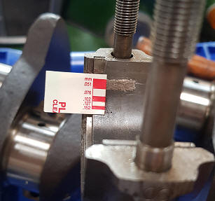
With plastigage, the clearance between plain bearings can be checked. Plastigage is a special plastic thread that must be applied to the area where the clearance is to be measured. Then, the bearing cap needs to be tightened, so the plastigage is crushed. The deformation of the plastigage is a measure of the clearance.
There are different colors of plastigage. Each color represents a different measurement range.
- Green: for a bearing clearance of 0.025 to 0.076 mm.
- Red: 0.050 – 0.150 mm.
- Blue: 0.102 – 0.229 mm.
- Yellow: 0.23 – 0.51 mm.
A measurement with plastigage is performed on this page:
Related pages: