Subjects:
- General
- crown pinion gear
- Operation of the differential
- Disadvantages of a differential
- Adjusting the crown pinion wheel
- LSD (Limited Spherical Differential)
- Torsen differential
- Differential maintenance and defects
- Adjusting the differential bearing preload
General:
The differential, also called the cardan, allows a speed difference in the drive. Only the term differential is used on this page.
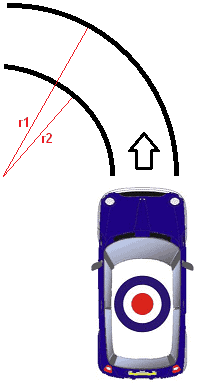
When cornering, one wheel makes more revolutions than the other. So when a car makes a left turn (as in the image below), the right wheels will make more revolutions than the left wheels (r1 > r2). So there is a speed difference. A differential ensures that this is possible.
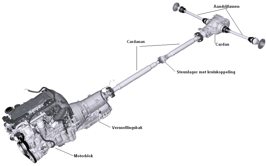
In front-wheel drive cars, the differential is located in the gearbox. On rear-wheel drive cars, this is located at the rear axle, between the rear wheels. A cardan shaft then runs from the gearbox to the rear, to the differential.
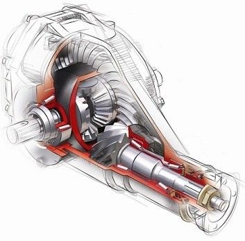
The image below is of a rear wheel drive car. The shaft between the gearbox and the differential (cardan) is called the cardan shaft or intermediate shaft. This is described separately on the page cardan shaft. Two drive shafts are mounted on the differential that drive the rear wheels.
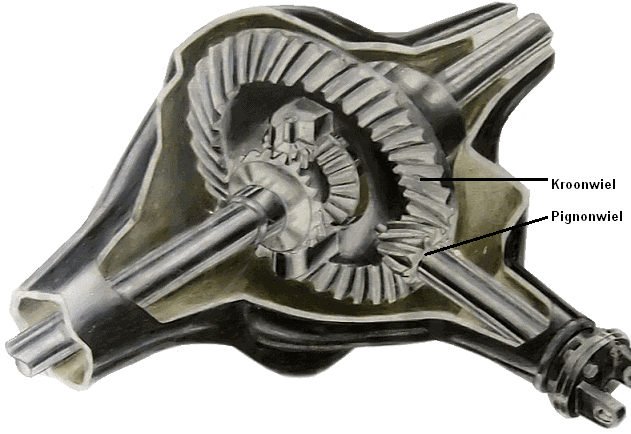
Crown pinion gear:
The crown pinion in the differential is mentioned separately, because these parts must be adjusted very accurately after work. The pinion wheel is attached to the cardan shaft. The motor and gearbox drive the cardan shaft and the pinion wheel drives the crown wheel. The adjustment between the crown pinion wheel is a very specialist task. The gears must be aligned with each other using the factory data and measuring / adjustment equipment. A good adjustment ensures the least noise development and the longest service life.
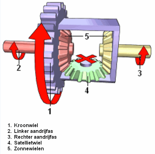
Operation of the differential:
The crown wheel 1 is driven by the pinion wheel from the engine/gearbox. When driving straight ahead, the drive shafts 2 and 3 will rotate at the same speed and the satellite wheel 4 will not rotate on its axis.
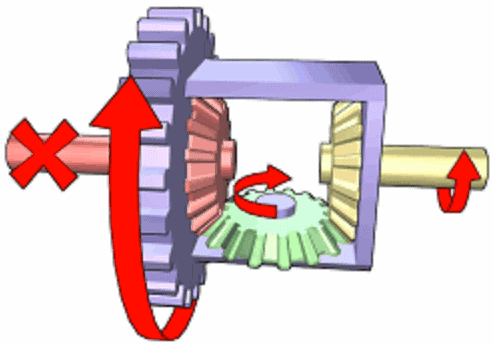
In the situation in this picture, the left drive shaft is stationary. This may be because the left wheel is on the asphalt and the right wheel is on a dirt road. In this case, the wheel on the dirt road will be slipping.
The satellite wheel now rotates on its axis and the full driving force is applied to the right-hand drive shaft. The left one is now stationary. A similar situation also arises when driving through a bend, the tire pressure is lower on one side, the tire profiles differ greatly and the road surface is not completely flat.
Disadvantages of a differential:
The fact that the differential allows differences in speeds between the wheels is also a major disadvantage under certain circumstances. When one of the driven wheels loses traction, the entire drive is lost. When a car with 1 wheel on the asphalt and 1 wheel in mud, the wheel that is in the mud will be 1% driven and the wheel on the asphalt (with the most grip) will remain stationary. This is because the satellite wheel will spin hard and the wheel with the least resistance will drive the most.
Crown pinion adjustment:
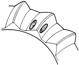
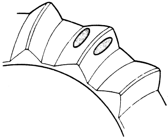
The height and distance of the crown and pinion mating surfaces can be adjusted. The images show the consequences of an incorrect adjustment.
By greasing the crown wheel a quarter of a turn with special grease (which dissolves in oil), the bearing surface between crown and pinion wheel can be determined. By turning the pinion wheel back and forth a number of revolutions, the bearing surface becomes clear (see pictures). By adjusting and turning a number of times, the whole can be adjusted to the ideal support surface.
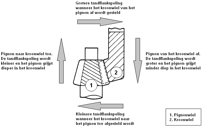
It must be taken into account that the load on the drive also causes displacement of the bearing surface. As the load increases, the bearing surface moves more to the outside of the crown wheel (above right image). With light loads, the bearing surface moves more inwards. When adjusting, the bearing surface should come to lie in the middle. Always refer to the factory data for the sizes.
An incorrect adjustment causes (sometimes extremely) a lot of noise in the drive, such as a whistling, screeching sound. The wear will also increase. For example, the differential can fail after a few thousand kilometers after careless (or not) adjustment. Of course there was a loud noise before that.
LSD (Limited Slip Differential)
In order to avoid the above situation, it is useful to (partially) switch off the operation of the differential in some cases. That's called blocking. When a differential is locked, the drive is the same on both axles. The satellite wheel is stopped, or both sun wheels are linked together. There are various developments with multi-plate couplings, viscous couplings and claw couplings.
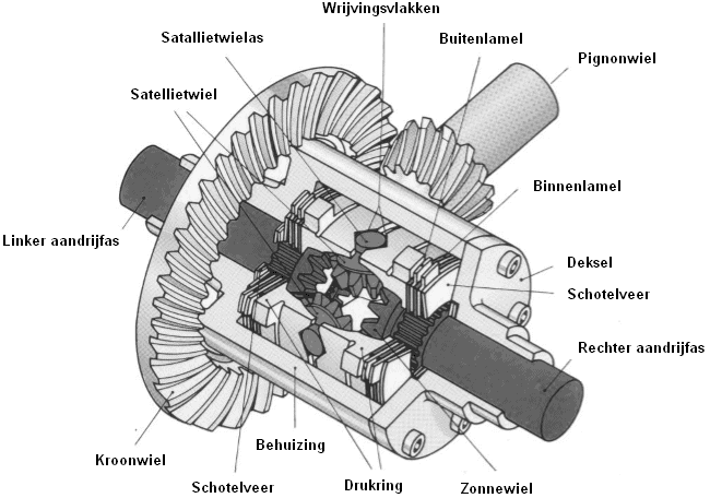
The image below shows an LSD (Limited Slip Differential). This is a differential with increased internal friction. Multi-disc clutches are fitted between the outer straight surfaces of the conical sun gears of the half-axles and the differential housing.
The pressure rings in the LSD are connected to the differential housing on the one hand, and axially displaceable on the other. The thrust washers are wedge-shaped on the inside due to the convex shape of the satellite wheels. The inner slats (dark colored in the picture above) engage with the internal teeth in the teeth of the stub axles. The external teeth of the outer blades engage in the longitudinal grooves of the differential housing. This prevents the outer slats from turning.
When driving straight ahead, the crown wheel and the drive shaft rotate at the same speed, so there is no friction. When one of the wheels has too little grip and therefore turns faster than the other wheel, a speed difference is created between the conical surfaces of the pressure ring. The thrust ring is pressed against the fins and a load dependent frictional moment is created between the outer fins (which are blocked by the differential housing) and the fast rotating inner fins connected to the drive shaft.
The more modern electronically controlled systems have been further developed on the self-locking systems. The previously described pressure rings present in the self-locking systems are then replaced by hydraulically operating ring cylinders. The multi-disc clutches are operated with the aid of electronics.
Torsen differential
The Torsen differential ('torsen' is a shortening of 'torque sensing', loosely translated: 'torque feeling') is in principle a symmetrical differential. When both output shafts rotate at the same rotational frequency, the drive torques in these shafts are equal. If differential action occurs for any reason, the drive torque to the faster rotating output shaft decreases and to the slower rotating shaft. Here too, in principle an internal friction moment is created that on the one hand reduces the output torque and on the other hand increases the output torque. The operation is based on the self-locking behavior of the worm gear transmission, which is created by choosing the correct pitch angle of these gears.
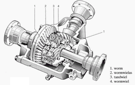
The axle differential shown in the picture below is bolted to the crown wheel. The worm gear shafts are mounted in the differential housing. The worm gears, which are connected in pairs by cylindrical gears, can rotate freely about their axes.
Three sets of two worm gears each are built in. One worm gear from each set engages the worm splined on the wheel drive shaft to the right wheel; the other worm gear engages the worm on the wheel drive shaft to the left wheel.
While driving straight (forward or backward), if there is no differential action, both axles rotate at the same speed. The differential housing takes the worm gears with it, which in turn drive the worms with the wheel drive shafts. Due to their pitch direction, the two worm wheels want to rotate in the same direction, which is not possible due to the coupling with cylindrical gear wheels. The differential now rotates as one block and ensures a symmetrical torque distribution (50 % – 50 %).
When a differential action occurs, for example when driving through a bend, or if one wheel slips, one worm will rotate faster and the other worm slower than the differential housing. A greater torque is now supplied to the slower rotating wheel than to the faster rotating wheel. The faster rotating worm drives the respective worm wheel and thus the worm wheel that drives the worm to the slower rotating wheel. To the slower-rotating wheel, the torque is additionally increased by the partially self-locking effect when driven by the worm gear in the direction of the worm. By choosing the correct pitch angle on the worm, the desired torque distribution, in this case the blocking value, can be obtained.
The Torsen differential has no influence on any ABS function, as the locking only occurs under load, i.e. when accelerating.
Especially in racing, with drifting, the differential is locked. If this is technically not possible on certain cars, the satellite wheel is welded to the sun wheels. In this cheap way the differential is always locked. The disadvantage is that it can hardly be driven on public roads anymore, because the wheel that makes the fewest speeds in bends will slip. There is also a greater chance of defects on the drive shafts and CV joints.
Another way is to let the ESP (Electronic Stability Program) intervene. This system brakes the slipping wheel by briefly engaging the brake caliper. By braking the slipping wheel, the action of the differential will automatically transfer more power to the other wheel. In this way, that disadvantage is also eliminated. This is sometimes also referred to as an electronic differential lock operation.
Maintenance and defects on a differential:
Nowadays, a differential often contains “lifetime oil”. The manufacturer indicates that the oil does not need to be changed periodically. Some manufacturers do indicate a drain interval in a certain number of kilometers. This term may not be exceeded. It is also good for the differentials with lifetime oil to change the oil every now and then. Every oil comes into contact with oxygen and starts an oxidation process with it. The lubricating effect decreases. That is why it is good to change this oil at a certain mileage (e.g. at 150.000 km).
Defective differentials, where the bearings are defective, or the space on the crown pinion is not correct, will make a lot of noise in the drive. Usually the differentials can be overhauled. During the overhaul, the tooth surfaces of the crown and pinion wheel are measured and the bearings replaced. If the tooth surfaces are too worn, the parts will have to be replaced. Replacing the crown wheel is often very expensive.
Adjusting the differential bearing preload:
The bearings in the differential must be mounted under a certain preload. This value is determined by the differential manufacturer. Both too low and too high a preload can cause the bearing to fail over time. Think of an axial load that is too high, which can cause the bearing to become too hot. When overhauling the differential or replacing the bearings, the preload must therefore always be checked and adjusted if necessary. By performing measurements it can be determined what thickness the washer (between the bearing and the retaining ring holder) should be.
Below are examples of the measurements to be performed.
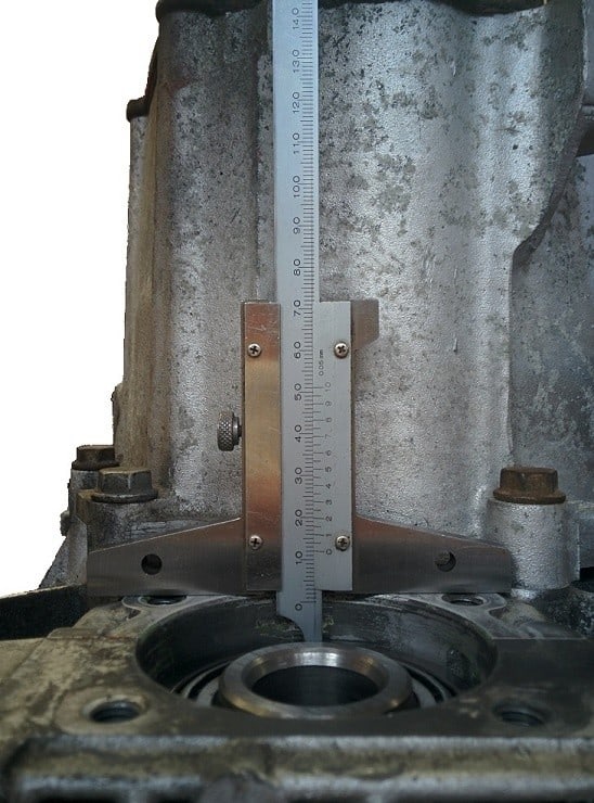
With a depth gauge the distance should be measured between the outside of the gearbox housing and the bearing. The value measured in the photo is 12 mm.
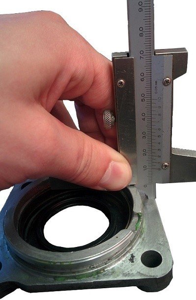
With this depth gauge the height of the chest of the seal holder can also be measured. The value measured in the photo is 10,0mm.
When mounting, the shoulder of the seal retainer is mounted in the differential housing. By subtracting the two values just measured from each other, the distance between the differential bearing and the shoulder of the seal holder is determined: Depth – height = 12,0 0mm – 10,00 mm = 2 mm.
When a 2 mm shim is placed between the differential bearing and the seal retainer, the bearing would be mounted stress-free.
That is of course not the intention; a thicker washer will have to be placed to mount the bearing under tension. The preload is specified by the manufacturer. This can be, for example, 0,25 mm.
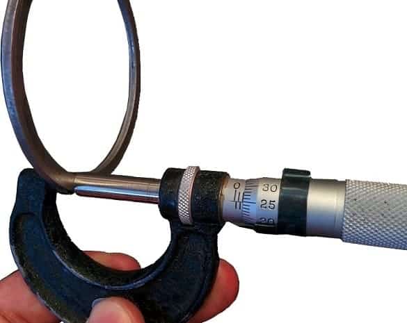
The spacer that must be placed in this case is the measured distance + the pretension, so; 2mm + 0,25mm = 2,25mm. When the shim with a thickness of 2,25 mm is placed, the preload is correctly set. The suitable shim must be found in a container with different sizes of shims. The correct washer can be found with a micrometer.
The image below shows that the shim has a thickness of 2,25 mm. So this is the correct washer. More information about measuring with the micrometer can be found on the page “Mechanical Measuring Tool".
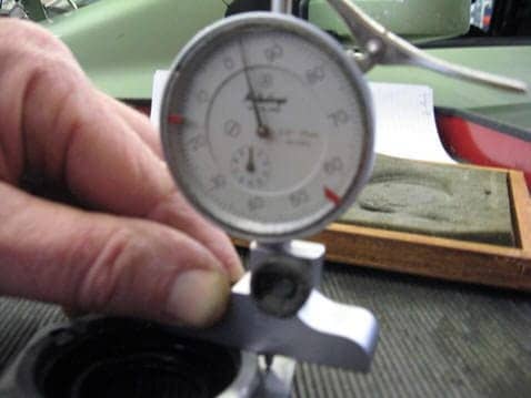
The measurements of the depth of the bearing and the height of the breast of the seal holder in the above images were taken with a depth gauge. However, these measurements can also be performed with a dial indicator. Explanation of measuring with the dial indicator is also given on the page “Mechanical Measuring Tool".
The readings in the images below do not match the above measurements. Also the pictures are very blurry. These will soon be replaced by new images showing the measurements correctly.
The values of the dial indicator and the depth gauge must match. So in principle it does not matter with which tool the measurement is performed, provided that both measuring tools are available. For example, during a practical exam, it is best that only one type of measuring tool is made available. It is therefore important to be able to work with all measuring tools; the caliper, the micrometer and the dial indicator.