Hydraulics introduction:
Hydraulics is the transmission of energy (forces and movements) by means of a fluid. The word “hydraulics” comes from Greek (hydro = water, aulos = pipe). Hydraulics is a drive, control, and regulation technology that we encounter in motor vehicle engineering, mechanical engineering, drive and control engineering, aviation, and agriculture. We can distinguish between hydrokinetic and hydrostatic drive systems:
- Hydrokinetic: high fluid speeds and relatively low pressures, such as the torque converter in the automatic transmission;
- Hydrostatic: low fluid speeds and high pressures, such as what we encounter in power steering.
In practice, in addition to hydraulics we also find pneumatics, electronics, and mechanical drive technology. Each technology has its own advantages and disadvantages for the application it is used for. The advantages and disadvantages of hydraulics compared to the other technologies are:
Advantages:
- High power density; large forces and torques can be transmitted with small component dimensions;
- Continuously variable speed, force, and torque;
- Hydraulic energy can be stored and reused;
- High accuracy and constant positioning are possible.
Disadvantages:
- Relatively expensive technology;
- Sensitive to contamination;
- Possibility of leakage (both internal and external).
In a hydraulic system, fluid is displaced. The fluid flow can be set in motion by means of a pump or a piston. All hydraulic systems are based on Pascal’s law:
“pressure applied to a fluid at rest is transmitted uniformly in all directions in a closed vessel”.
We see this principle in the following image, where a piston applies a force (F1) to the piston surface. The force creates a pressure in the (closed) fluid-filled system, which pushes the piston upward with force F2.
The pressure depends on the force and the surface area of the piston. On the page “pressure in the hydraulic system” this is made clear by means of animations and calculations.
Hydraulic schematics:
Hydraulic schematics created using symbols are compiled by the manufacturer so that during maintenance and/or repair work you can see how components are connected. The flow diagram also indicates which types of components are in the system. An overview of the symbols can be found on the page with the hydraulic symbols list.
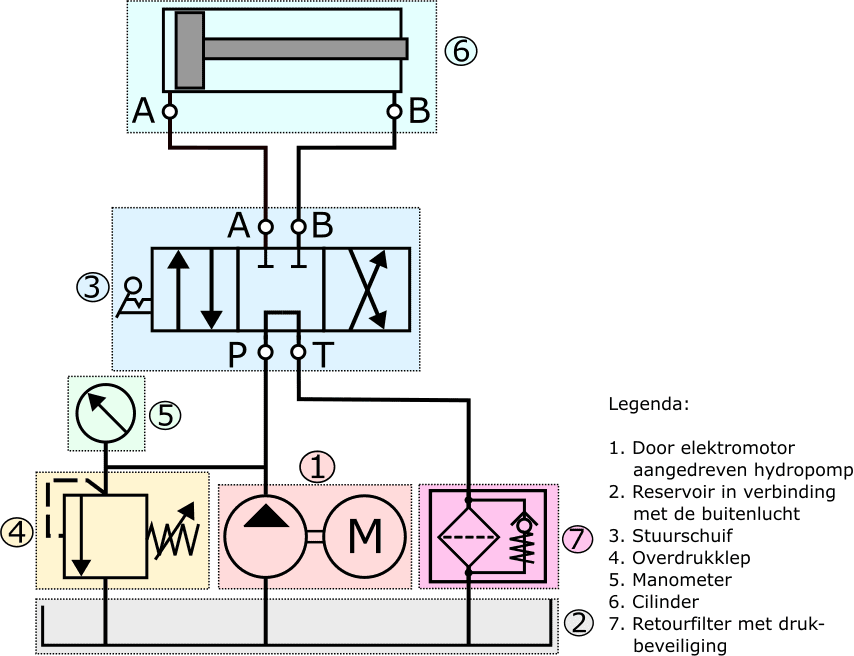
In the following image we see the most commonly used components in a hydraulic system. The components are shown with a color and number.
An electric motor drives the hydraulic pump (1), which moves the hydraulic oil to the directional control valve (4).
The pressure relief valve (2) protects the system against excessively high pressures. The system pressure can be read on the pressure gauge (3).
The manually operated directional control valve has four ports:
P (pump), T (tank), and ports A and B for the cylinder.
The directional control valve can be set to three positions:
- at rest (current position);
- to the right;
- to the left.
Depending on the position of the directional control valve, the cylinder is supplied with hydraulic oil and the piston will move.
The following images outline the different positions of the directional control valve that can be used to move the cylinder.
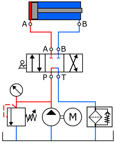
1. Directional control valve in neutral position:
The hydraulic pump in the following schematic is also driven by an electric motor. The pump draws hydraulic oil from the reservoir and delivers the oil under increased pressure to the pressure relief valve, the pressure gauge, and the directional control valve.
The directional control valve is in the center position, which connects ports P and T, and the hydraulic oil enters the directional control valve via P and exits via T.
From port T, the hydraulic oil flows through the return filter to the reservoir. In the housing of the return filter there is a pressure protection device, which opens against spring force when fluid pressure increases.
The pressure increase can occur when the filter becomes clogged by dirt particles.
Because the hydraulic oil circulates in this position of the directional control valve, there is hardly any pressure build-up. There is only a certain degree of resistance that the oil encounters in the directional control valve, the lines, and the return filter. However, this resistance is so low that the oil is pumped around without pressure.
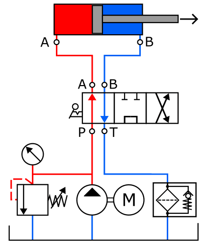
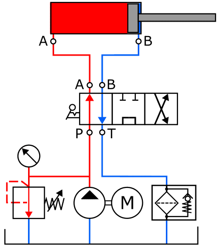
2. Directional control valve in left position:
The directional control valve is set to the left position. Ports P and A, and also T and B, are connected to each other in this position. The hydraulic oil moves through the lines to the left side of the cylinder. Pressure build-up on the left side of the piston starts and is now controlled.
Because the return (B) of the cylinder is now connected to the T port of the directional control valve, the oil on the right side in the cylinder can flow to the reservoir – via the return filter.
The cylinder makes an outward movement until the end stop is reached. We see this in the next situation.
3. Piston in extreme position:
In this situation the piston is extended to the maximum, so the end stop has been reached. The overpressure protection prevents the pressure from rising too high. Without this protection, the pressure would rise uncontrollably, resulting in damage.
The pressure control valve (in the image it is shown to the left of the hydraulic pump) opens when the preset pressure is reached. The pressure relief valve connects the supply line from the hydraulic pump to the return. There is now constant circulation through this pressure relief valve until the pressure decreases.
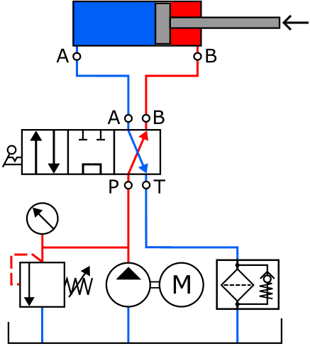
4. Directional control valve in the right position:
The directional control valve is now operated in the right position (opposite). Compared to situation 2, the lines are cross-connected: P is now connected to B, causing pressure to build on the right side of the piston. Port A is connected to T (return). In this position of the directional control valve, the piston moves to the left.
When the piston reaches its end stop, the pressure build-up will rise again until it reaches the pressure at which the pressure relief valve opens. The directional control valve must then be returned to the center position.
Related page: