Blower Motor:
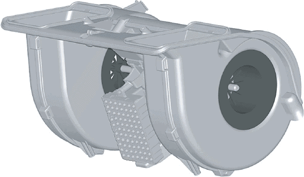
The image below shows a blower motor. This component is also referred to as a heater blower or simply as the blower.
In the center of the blower are the blades that push ventilation air into the interior. Air is drawn in at the side of the motor and blown through the above oval-shaped channels, through the heater core or air conditioning evaporator (which are mounted directly after the blower motor in the heater housing).
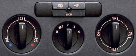
The images below show the manual control panel (left) and the automatic (right). The advantage of the automatic system is that fan speed, outlet temperature, defogging, and recirculation are all automatically adjusted to current conditions.

Duty-cycle controlled blower motor:
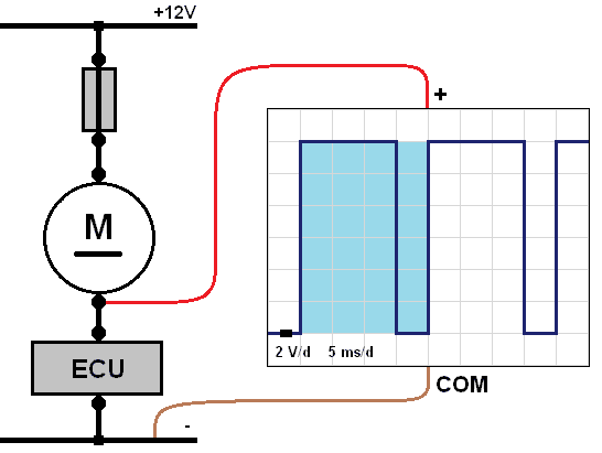
Modern ventilation systems are increasingly equipped with a duty-cycle regulated blower motor. The main advantage of this control is that no energy is wasted, as it is with a conventional heater resistor. With a duty-cycle controlled blower motor, the ECU (control unit) rapidly switches the electric motor on and off. We can measure this with an oscilloscope.
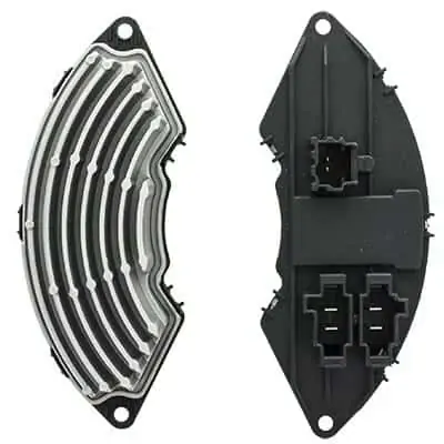
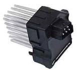
The bottom left image shows both sides of the switching section of the heater motor. This component is mounted onto the blower motor. The housing contains a switching transistor controlled by the ECU. The switching transistor supplies either power or ground to the electric motor. The transistor gets very hot during use. The cooling fins dissipate the heat into the airflow moved by the fan.
The image to the right shows the scope pattern—the period (in blue) is displayed.
- Switched off when the voltage on the ground side is 12 volts during that period. The electric motor does not draw voltage.
- Switched on when the voltage on the ground side is 0 volts in that period. At that moment, the electric motor draws the full 12 volts to run.
The on-time is 25% of the total period, so the blower motor runs at a low speed. The longer the electric motor is switched to ground, the harder the fan will blow. If the ECU grounds it fully, the fan will run at maximum speed. More explanation about control methods and signal processing can be found on the duty cycle and PWM control page.
Possible faults in the duty-cycle controlled system:
- ECU input not functioning, such as the control unit where switches and buttons are located. This may use LIN bus communication. Check if communication is present.
- ECU power supply (positive or ground) faulty. The ECU does not switch on.
- Blower motor supply voltage not correct. Check whether the blower is switched on the positive or on the ground side and verify this by measurement. In the above diagram, the electric motor is ground-switched, so with ignition on, there should always be 12 volts at the motor input terminal.
- Faulty switching section. First check the wiring—are power and ground at the switching module correct? Is there communication with the ECU? The ECU is often located behind the control buttons. If all measurements are correct, but the switching module does not drive the electric motor, the switching module with transistor may need replacement.
Control of the blower motor using a resistor block:
The blower motor, of course, needs to be powered to operate. At 12 volts, the fan will run at maximum speed, which matches setting 4 on the dial (or the maximum digital value on an automatically controlled system). If positions 1, 2, or 3 are selected on the control switch, the blower motor must run slower. The voltage must then be reduced, which is done by the resistor block. The three images below show different heater resistors.


The heater resistor becomes very hot; therefore, it is located in a duct where air flows through. It is often near the blower motor or even inside the same housing. The passing air cools the resistor block.
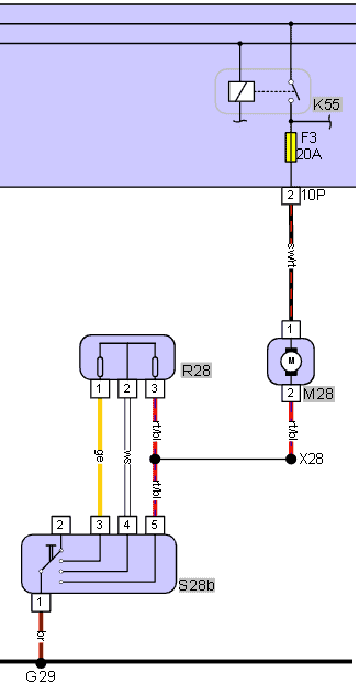
The diagram of the blower motor shows the following components:
- K55: blower motor relay
- F3: 20 A fuse
- M28: blower motor
- R28: resistor block
- S28b: four-position switch
Connector codes and labels are also shown:
- 10P, 2: connector to electronics box, position 2
- X28: wire connection
- G29: ground point
Wire color abbreviations are as follows:
- sw/rt: black/red
- rt/bl: red/blue
- ws: white
- ge: yellow
- br: brown
The positive supply wire for the blower motor is connected via a fuse to the relay. The relay is energized when the ignition is switched on, so with ignition on, the blower motor always receives a positive voltage. Current flows via the resistor block and the switch to ground. The blower motor is therefore ground-switched.
The blower speed depends on how many resistors current flows through.
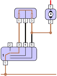
Below are three situations in which the switch connects the blower motor to ground.
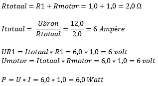
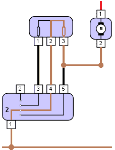
Position 1: The switch is set to position 1. Current flows via terminal 3 of the resistor block, through two resistors in series. The two resistors together cause a voltage drop of 8 volts (with a system voltage of 12 volts). The formula below shows that the blower motor runs at 4 volts in this position.
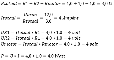
Position 2: When the switch is in position 2, the current flows through only one resistor. The formula changes slightly since the value of R2 is omitted. With less voltage drop, the blower motor runs at higher voltage and current. It will run faster.
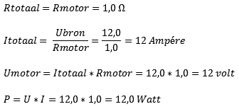
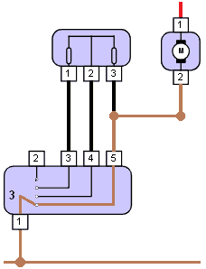
Position 3: In this setting, the resistor block is not used. Current leaves the motor and goes directly to the switch. This grounds the blower directly. It now operates at its highest speed. The formula below takes into account the internal resistance of the electric motor. The voltage across the motor is now 12 volts.
Diagnostics: Blower motor with resistor block and seven possible faults:
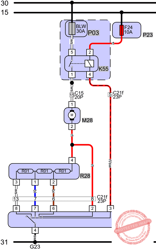
The previous section explained how the heater resistor block controls blower speed. This section treats possible faults and explains how to diagnose them with electrical measurements, using the adjacent wiring diagram.
- At the top of the diagram are terminal 30 (constant +) and terminal 15 (switched +)
- Below them are P03 and K55 (fuse and relay), next to an additional fuse (P23) in the fuse holder
- Pin 1 of the relay (DIN code 87) supplies power to blower motor M28
- The blower motor M28 is in series with the resistor block R28
- The switch position S28b determines through which, and how many, resistors ground is connected to the motor
- In position 4, the motor is connected directly to ground without a resistor in series, and runs at maximum power
- In positions 3 through 1, another resistor is added in series each step, making the motor run more slowly
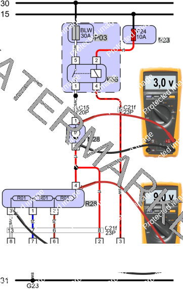
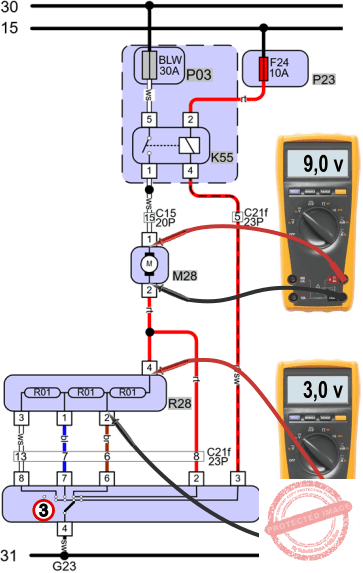
The images below show voltage measurements in the four switched positions when there is no fault. It is clear that with the switch at position 1, a lot of voltage (9 volts) is dropped across the resistors, leaving only 3 volts for the motor to run.
In positions 2 and 3, less voltage is suppressed by the resistors because the current flows through fewer of them.
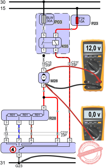
In position 4, current bypasses the resistor block; no voltage is dropped by the resistors anymore. The motor runs at the full 12 volts.

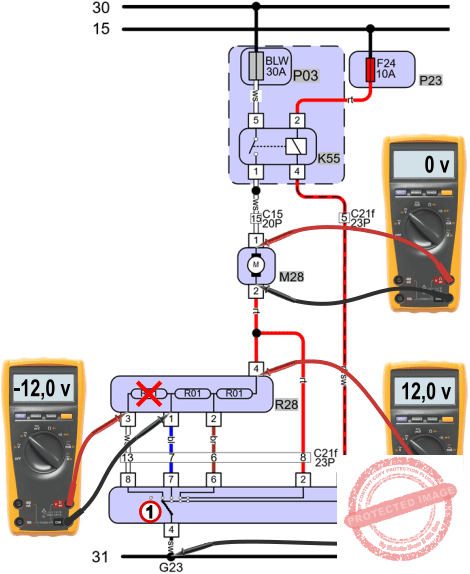
Fault 1: Fan doesn’t work on position 1 but works in other positions.
A heater resistor can fail due to heat. A common result of a faulty heater resistor is that the blower only works on position 4 and stays off in other positions. In this case, one resistor is faulty. By measuring voltages, we can determine which resistor is burned out.
- The voltage across the blower motor is 0 volts, which is why it does not operate at all
- The voltage difference across the resistor to ground is 12 volts, indicating an open circuit somewhere along the path
- The voltage difference across the left-most resistor is -12 volts, measured from pin 3 to pin 1. This confirms an open circuit between these two points
- The value is negative because the voltage at the black probe is 12 volts higher than at the red probe
- Conclusion: the heater resistor is faulty and needs to be replaced
Important: While measuring voltages, the blower must be switched on and the switch must be set to the faulty position. Do not set the blower to position 0 or 2 while measuring the voltage across the resistor for position 1. It may seem obvious, but in practice this is sometimes overlooked.
Fault 2: The fan runs too slowly on position 1:
When switching to any of the four positions, you may notice the fan runs more slowly than it should. This can happen in position 1, as in this example, or in position 2. In that case, the fan in position 2 could run just as slowly as in position 1.
This is due to a resistance in the wire between the heater resistor and the switch.
- The voltage drop across the blower motor is 2 volts. In a no-fault situation, this was 3 volts, so due to the lower voltage, the motor runs more slowly
- The voltage drop across the heater resistor is 9 volts, which means voltage is absorbed in the resistors—but this does not indicate a fault
- The voltage drop across the white wire, between pin 3 of the resistor and pin 8 of the switch, is 1 volt. This loss is due to contact resistance
- Because of the voltage loss in the wire, less voltage remains for the blower motor, so it operates at reduced speed
- Conclusion: The white wire is damaged and needs to be repaired

Fault 3: The fan blows too weakly in all positions:
If the blower is too weak in all positions, this may indicate a defective blower motor. In that case, set it to position 4 and measure the voltage across the motor. This should (according to V4-measurement theory) roughly match battery voltage. In the figure below, the voltage in position 4 is only 7 volts due to a 5-volt loss in the ground wire between the switch and the ground point. This 5-volt drop is also measured between pin 2 of the motor and G23 (ground). The affected wire is shown in the image.
If a wiring resistance is present and the switch is not set to position 4 but to position 3, the diagnosis can become unnecessarily complex. A resistor is then intentionally switched in series to reduce motor speed, so there is both a contact resistance as a fault and a resistor in series to slow the fan intentionally. The last two images show voltage drops in position 3.
Conclusion: If the blower is weak in all positions, set it to the highest speed (so the resistor block is not in series) and perform the V4-measurement across the battery (V1) and the blower motor (V2), followed by V3 and V4 if V2 differs by more than 0.5 volts from V1. Read more at: measuring with the multimeter.


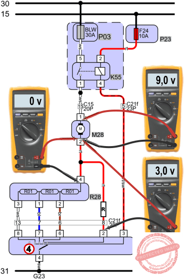
Fault 4: Fan doesn’t work in position 3, works in other positions
This complaint resembles fault 1, but in this case, there is a wire break between the heater resistor and the switch. With a V4 measurement, the voltage drops become clear. Since the V4 measurement is assumed to be known, V1 and V3 are omitted here.
- The voltage drop across the motor (V2) is 0 volts
- The drop across the ground (pin 2 of the motor vs. a ground point) is 12 volts, indicating an open circuit
- The measurement between pin 2 (resistor) and pin 6 (switch) is a 12-volt difference. This wire is broken
- Conclusion: The brown wire between pin 2 and 6 is broken and must be repaired
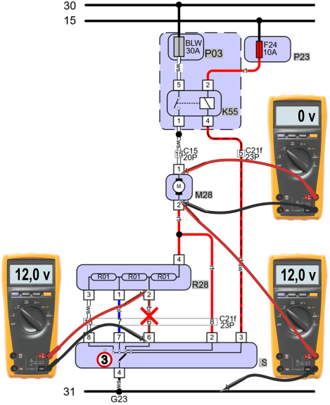
Fault 5: Fan works fine in positions 1, 2, and 3, but in position 4 it blows just as hard as in position 3.
There is no difference in fan speed between position 3 and 4. Where 3 volts should have been dropped across the resistor in position 3, those 3 volts are now lost at a contact resistance between the blower motor and the switch. The symptom helps locate the resistance: since the fault isn’t present in other positions, it must be located after the splice point.
Conclusion: The wire between the splice point and the switch is damaged and needs to be repaired.
Fault 6: Position 4 does not operate.
In positions 1 to 3, the blower motor works fine. A V4 measurement in position 4 shows: V2 0 volts and V4 12 volts, so a 12-volt drop in the ground, indicating an open circuit. Between pin 2 of the motor and pin 2 of the switch, a measurement of 12 volts confirms the break.
Just like the contact resistance in fault 5, the break must be to the right of the splice point, since the blower works in other positions.

Fault 7: Blower motor does not work at all.
If the blower motor is completely inoperative, first check voltage differences using the V4-measurement in position 4. The following voltages are measured:
- V1 (battery): 12 volts
- V2 (blower motor): 0 volts
- V3 (loss +): 12 volts
- V4 (loss -): 0 volts
These values indicate an open circuit between the positive side of the battery and pin 1 of the motor.
A relay measurement (pin 5 vs pin 1) shows a value of 12 volts. The relay contact is open, which is the “cause” for the result of the V4-measurement. The relay does not switch power and current to the blower motor—this is, in effect, the open circuit.
Measurements on the relay control side must clarify whether the relay is being triggered or not. In order for coil current to flow between pin 2 and pin 4, pin 4 must be switched to ground by the switch. In a properly working situation, the voltage between pin 4 and a ground point should be around 0 volts.
In this case, a voltage of 12 volts is measured across the relay control wire, so the relay cannot be triggered by the switch and does not pass current to the blower motor.
Conclusion: Control wire between pin 4 of the relay and pin 3 of the switch is broken.
