Introduction:
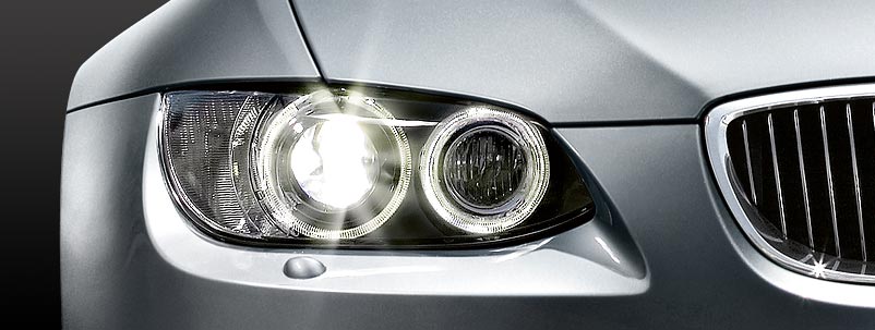
The headlamps provide illumination at the front of the car. Some cars have all the lights in one housing (like the car in the image below) and others have multiple units. The mandatory front lighting consists of: parking lights, low beams, high beams, turn signals, and optionally fog lights and daytime running lights. The choice of bulbs includes incandescent bulbs, halogen bulbs, xenon, and/or LED.
Colors:
The parking lights must be yellow or white when lit. Standard halogen bulbs are used. Bulbs with a blue coating are intended to emit as white as possible (e.g., with xenon). Low beams and high beams must be yellow or white. Xenon bulbs often appear blue/purplish, but on the headlamp beam setter, the light pattern is often still just white. Other colors are not allowed.
Front turn signals may be orange, yellow, or white. Fog lights have the same requirements as low beams and high beams; they must be yellow or white.
Daytime running lights may only be white in color. In America, the “daytime running lights” are often orange in color and constantly lit when the main lighting is off. In the Netherlands, this is prohibited, and the orange lights must be replaced with white ones. If that’s not possible, they should be switched off. This often results in another problem if the daytime running lights and turn signals are combined; then the only solution is to install white lights. White turn signals, after all, are allowed.
Xenon lamps are often equipped with headlamp washers in the headlamp housing or in the front bumper. This is to prevent stray light from, for example, dirt and insects on the headlamp glass.
H4 and H7 bulbs:
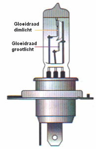
The most commonly used bulbs are the H4 and H7 bulbs. At the bottom left, an H4 bulb is shown. This bulb has two filaments in a row; one for low beam and one for high beam. When the low beam is switched on and the driver flashes (or the high beam is switched on), the low beam temporarily switches off.
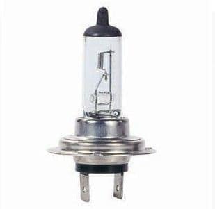
At the bottom right, an H7 bulb is shown. This bulb has only one filament; it is solely for low beam. A separate bulb is needed for the high beam.
The H4 bulb is much thicker than the H7 bulb, so they cannot be mistakenly swapped in the headlamp housings. The H4 bulb has three connectors on the plug, while the H7 bulb has two.
Reflectors:
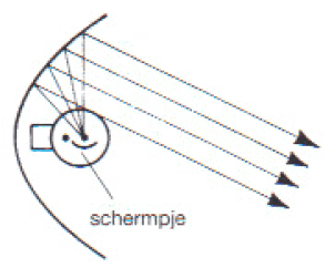
Low Beam Reflector:
The low beam lamp shines upward, against the top of the parabolic reflector. This reflector reflects the light back at a specific angle. These light rays naturally need to be directed downward. There are people who install the bulb upside down in the headlamp (with force, because it’s not really possible otherwise). The light rays then go upwards and blind all oncoming traffic.
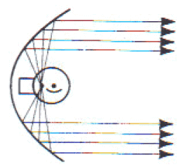
High Beam Reflector:
The high beam bulb emits light in all directions, upwards and downwards, left and right. The reflector reflects the light rays straight forward, creating a large air bundle. The light output is now maximum, but very annoying for oncoming traffic who get blinded.
Low Beam Light Pattern:
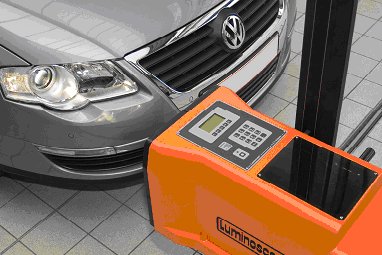
The light pattern of the car is measured and adjusted if necessary during a major service and APK (Dutch vehicle inspection). A beam setter is placed in front of the headlamp, where a little screen measures the light incident. Based on the light pattern in the beam setter, the headlamp can be adjusted by adjusting the mechanisms in the headlamp. Fog lights can also be adjusted in this way, but this is usually only done after dis-/reassembling or replacing the fog lamp units.
Below are four different light patterns displayed (with light pattern 1 as an example of a high or low setting). The other three light patterns are commonly seen in practice. If a headlamp is rejected during the APK due to a poor light pattern because of weathered headlamp lenses or reflectors, many people don’t know how that is determined by the inspector. These images make it much clearer. There’s also a borderline case shown, which can just about pass the inspection.
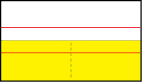
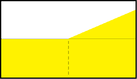
Light Pattern 1:
This is only the horizontal line. The black dotted line indicates how far the light (yellow area) may come. It is usually between 1.0% and 1.5% for cars without xenon and about 2% for cars with xenon. The upper red line indicates where the light pattern would be if the headlamps were set at 0% (too high). The lower red line indicates a too low light pattern (e.g., 3%). It may also be that in this case, the adjustment motor is set too low, which can be regulated in the interior. This must always be set to 0 before adjusting.
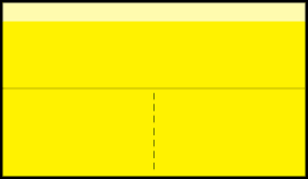
Light Pattern 2:
A perfect light pattern. A good height, with a light arc on the right side that shines towards the roadside. This is always the case for cars driving on the right-hand side of the road. For English cars, this light arc is directed to the left. That is why there are often stickers on the headlamps of English cars when they go to another country. This is purely to shield this light arc, to prevent blinding of oncoming traffic.
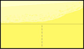
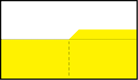
Light Pattern 3:
For cars with weathered headlamp lenses or reflectors, the light pattern often looks like this. There is a lot of scattered light; there is a lot of light present at the top side of the separation line. Sometimes it is so severe that no separation line is visible anymore. The headlamp then in principle beams in all directions, while the light output (and thus the visibility) is also minimal. It’s up to the inspector to decide if it’s rejection, or if it’s still acceptable.
If a horizontal separation line is still visible (as in this image) it may just be approved.
Light Pattern 4:
If the bulb is mounted upside down in the headlamp, the light does not shine down but upwards. This is clearly visible in this image. See the image on the right.
American Headlamp:
American headlamps differ from European versions. They often have an orange reflector or additional orange lighting built-in, which is not present in the European version. Also, the turn signals are constantly lit (if the turn signals aren’t on, other amber lights have been added to the vehicle). The amber lights turn on as soon as the car is switched on (like daytime running lights). In the Netherlands, this is not allowed. The amber lights may only be used as turn signals and must not stay on constantly. Even if they are driven at only 50%, it’s a reason for rejection during the APK and reason for a fine during a traffic check.
Another difference between the headlamps is the light pattern. The light pattern of an American headlamp runs, contrary to European guidelines, horizontally on the right side of the light pattern. The light pattern rises slightly from the middle and then runs horizontally to the right. The headlamp now, therefore, shines more straightforward than it shines into the roadside. For imported cars, this can sometimes cause a problem. In principle, this is not according to European requirements, so the inspector could consider this as rejection. This also purely depends on how high the line is on the right side compared to the left side.
Headlamp Height Adjustment:
The headlamp height is adjustable so that they can be lowered when the vehicle is loaded. The tilt motor, also known as the mirror adjustment motor or adjustment motor, ensures the reflector inside the headlamp tilts vertically on its axis.
The three systems to adjust headlamp height are:
- Static height adjustment. The driver operates the adjustment with a knob on the dashboard.
- Dynamic height adjustment. This height adjustment reacts to body movements.
- Semi-static height adjustment. The sensors on the control arms register the vehicle’s load. When the vehicle is loaded at the rear, the rear of the vehicle lowers and the headlamps shine upwards. The semi-static height adjustment then adjusts the headlamps downwards.
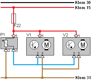
The diagram on the right side is of the static headlamp height adjustment. It is a “waterfall” type diagram with the positive (terminal 30) at the top and the ground (terminal 31) at the bottom. The circuit is protected by fuse F22. The potentiometer (P1) is the adjustment knob that the driver can turn. The potentiometer is a variable resistor and has a positive (pin 1), ground (pin 2), and signal wire (3). The voltage on the signal wire depends on the position of the potentiometer’s slider. The slider is indicated by an arrow on the resistor. The voltage arrives via the blue wire at adjustment motors 1 (V1) and 2 (V2). The electronics of the adjustment motors (indicated by the transistor symbol) will adjust the motors to the desired position.
In the diagram, each adjustment motor is shown with only a positive wire, ground wire, and signal wire.
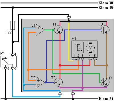
The control unit reads the position of the adjustment motor and then activates it to set it in the correct position. The diagram below shows what actually happens inside the control unit. The diagram and text refer to the left adjustment motor (V1).
Inside the control unit are two opamps and four transistors, configured as a differential amplifier. Depending on the voltage difference that occurs between the potentiometers in the dashboard and in the adjustment motor, the transistors are driven by the opamps. This voltage difference arises, for instance, when the driver turns the adjustment wheel (P1) downwards. The slider on the variable resistor assumes a different position. As a result, more or less voltage is lost in heat. The voltage on pin 3 of P1 therefore becomes higher or lower. This voltage comes through the blue wire to the two opamps (O1 and O2). The opamps measure the voltage difference between both potentiometers (P1 and V1), that is, between the blue and orange wires.
- At rest: When the voltage on the blue and orange wire is equal, the system is at rest.
- Adjustment wheel turned down: The transistors T1 and T4 are brought into conduction by opamp O1 when the voltage over the blue wire is higher than on the orange wire. The adjustment motor gets its power on pin 4 via the red wire (via T1) and ground on pin 5 via the brown wire (via T4). As a result, the adjustment motor will rotate clockwise until the voltage of its potentiometer has reached the same voltage as the potentiometer in the dashboard (P1). When no more voltage difference is present between the wires, the opamp will not put any voltage on the output.
- Adjustment wheel turned up: If the adjustment wheel is turned the other way by the driver, the voltage on the orange wire will become higher than on the blue wire. Now opamp O2 puts a voltage on the output. Transistors T2 and T3 now go into conduction. The adjustment motor now rotates anticlockwise, i.e., in the other direction because the polarity is reversed compared to the previous situation. The control stops when the opamp no longer measures a voltage difference between the sliders of the potentiometers.
Headlamp Wiring Testing and Connection:
The headlamp wiring harness can be damaged after a collision, incorrect installation causing the wiring to become pinched, or by the wiring harness rubbing against something. The wiring can become damaged or even break. To repair the wiring, in most cases, the same color cables can be connected together. A technician must be able to determine which wire has which function by reading the circuit diagram and performing measurements. At that point, the wires on the vehicle side can be connected to the headlamp wiring. This knowledge and skill are part of the practical exam for first-line technicians.
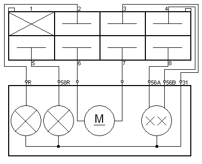
In the following electrical diagram, a lighting system for the front of a vehicle is shown. To the right of the diagram, the legend is displayed. It is a “waterfall” type diagram with the positives (terminal 30 and 15) at the top and ground (terminal 31) at the bottom. Multiple switches are shown connected to a control unit (A20). This ECU switches on the turn signals (E5 and E6) as well as the relays for the low and high beam lights. The parking/side light is switched on and off directly by the light switch (S21). Further, the headlamp adjustment motors (M01 and M02) are shown, which, based on the signal from the adjustment wheel with the built-in potentiometer, turn up or down.
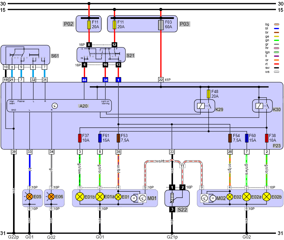
P02: fuse box for terminal 30;
P03: fuse box for terminal 15;
S61: steering column switch (turn signal and high beam);
S21: Light switch (parking and main lighting)
A20: Control unit;
K29: Low beam relay;
K30: High beam relay;
E05: Turn signal L;
E06: Turn signal R;
E01B: High beam L;
E02B: High beam R;
E01A: Low beam L;
E02A: Low beam R;
E01: Parking light L;
E02: Parking light R;
M01: Height adjustment motor left;
M02: Height adjustment motor right;
S22: Headlamp height adjustment wheel
G01: ground point left front;
G02: ground point right front;
G2*p: interior ground point
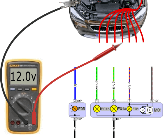
As described above, a technician must be able to connect the headlamp wiring by reading the diagram and performing measurements. To clarify, below is a step-by-step plan for connecting the (cut) wires on the vehicle side (often one color, in this case red) to the colored individual wires of the headlamp.
Parking/Side Light:
First, we check if with the lighting switched off, the voltage on all of the vehicle originating wires relative to ground is 0 volts.
In the legend, we saw that the code E01 belongs to the left parking light in the headlamp. With the voltmeter, we look for the positive wire of this lamp.
- Ground wire of the voltmeter: connect to a good ground point, preferably with a crocodile clip to a ground point intended for the battery charger;
- Positive wire: one of the six wires has changed from 0 volts to the board voltage (12 to 14 volts). We measure each red wire one by one and locate the respective wire. As a check, the parking light can be briefly switched off and on to see if the voltage alternates between 0 and 12 volts.
Low Beam:
We connect the parking light from the previous measurement to the or/bl (orange/blue) wire and switch on the low beam. Now the voltage of two wires amounts to 12 volts: the parking light (remains on) and the wire of the low beam. We locate this wire.
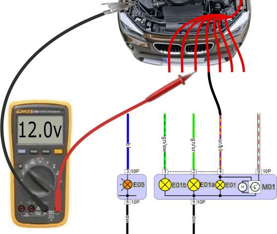
High Beam:
After the low beam wire is connected to the gn/or (green/orange) wire, we switch on the high beam. One of the remaining red wires has turned 12 volts. We connect this wire to the gn/sw (green/black) wire of E01b (high beam).
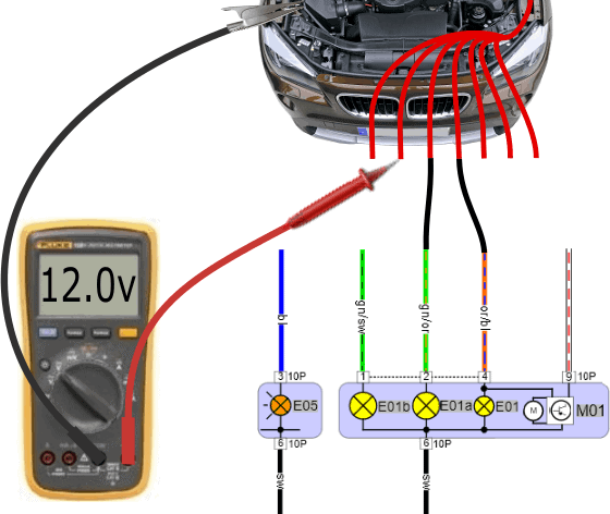
Turn Signal:
A voltmeter may be too slow to measure the alternating voltage between 0 volts (off) and 12 volts (on) when the turn signal is switched on:
- The voltage display on the display may fluctuate;
- “Infinite” or “overload” may appear on the display.
An oscilloscope could verify the block voltage, but this isn’t necessary. When switching the turn signal on or off, we see a voltage change in the display, giving us enough information that we are measuring the correct wire. We connect this wire to the bl (blue) wire of E05 (turn signal).
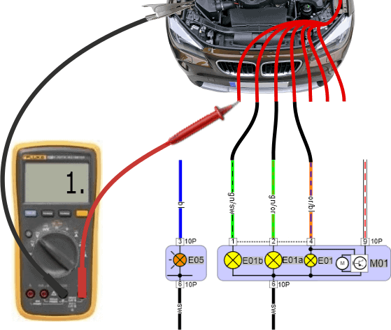
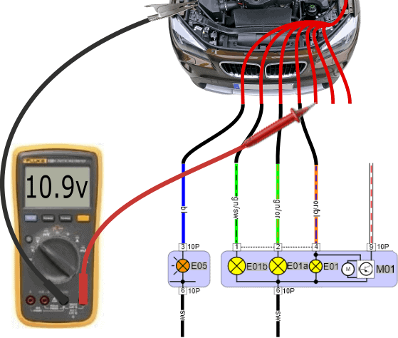
Height Adjustment:
On one of the wires, after switching on the parking or low beam light, a lower voltage is measured than the positive wires of the lamps. In this case, we measure 10.9 volts. With a different voltage value, we almost always deal with the signal wire for the headlamp adjustment motor.
Inside the interior (dashboard, steering column, instrument panel), is the adjustment wheel or digital button to move the headlamp adjustment motors up or down. In position 0 (headlamps are in the uppermost position), the voltage is often high. When we turn the adjustment wheel to position 2 or 3, the voltage on the signal wire to the adjustment motor decreases: receiving the command to move downwards. In position 3, the voltage can fall to 6 or 7 volts.
We then connect the wire for the height adjustment to the ro/wi (red/white) wire. Unfortunately, the color coding is missing from the diagram.
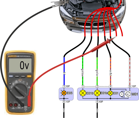
Ground (1):
So far, all positive wires have been connected, but without a ground wire/wires, the lamps and adjustment motor still do not function. The voltage on the remaining wire has remained 0 volts during all measurements. To make sure that the wires on which you measure 0 volts are ground wires, we perform a resistance measurement. This measurement is shown below.
Ground (2):
The resistance on the red wires relative to the ground point on the chassis is both 0.1 ohms. It can happen that the resistance value is slightly higher, e.g., 5 ohms. Now that we are certain that the last two red wires are attached to the chassis, we connect them to the black wires of the headlamp.
- Vehicles where the turn signal is in another unit or a different part of the headlamp often have two separate connectors (as in this diagram). Both connectors have a ground wire. These two ground wires are usually connected to the same ground point, so it does not matter if they are swapped;
- In vehicles with the turn signal inside the lighting unit, there is a ground junction in the headlamp where several ground wires come together and exit as a single ground wire.
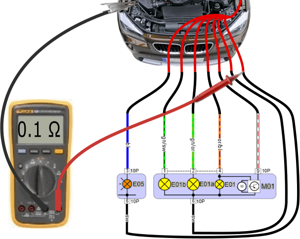
The resistance measurement is always conducted last. This is because sometimes a switched-off lamp is connected to ground on both terminals (plus and minus) through the switch. If one starts with the resistance measurement, a ground is measured on multiple positive wires. Only when the lamp is switched on does the ground change to a positive.
Ground-Switched H4 Lamp:
In this section, we’ve only discussed a positive-switched H7 lamp. This we recognize by the fact that the low beam and high beam lamps receive a positive (12 volts) on their respective wires to illuminate the lamps.
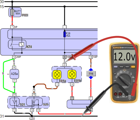
We can also come across a ground-switched H4 lamp. The following three diagrams (right and below) relate to a switched-off H4 lamp containing:
- E01a: low beam;
- E01b: high beam;
- S21: light switch;
- S25: selector switch between low and high beam;
- Ins: high beam indicator light in the instrument panel.
For a properly functioning lighting system, we measure the board voltage (around 12 volts) on both the positive and negative terminals in the switched-off position. Now the voltage difference over the lamp is 0 volts (on the plus and minus). No current flows through the filament. The lamp is off.
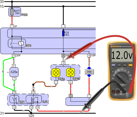
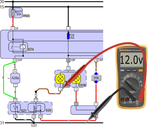
The switch S21 (light switch) provides the switch next to it (S25) with a power supply when the lighting is switched off. When, for example, the low beam is switched on, the switches S21 and S25 both switch to ground. The driver can switch the low beam or high beam to ground using S25 (often the turn signal lever on the steering column). One of the two lamps will illuminate.
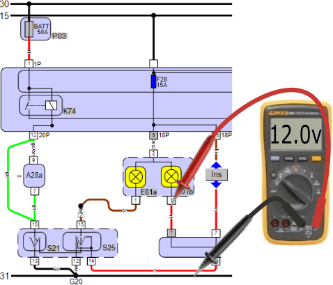
H4 Lamp Switched On:
The supply voltage of the lamps is again 12 volts. The negative terminals of the lamps (low beam brown, high beam red) are switched to ground via switch 25.
- Low Beam: when the low beam is switched on, the voltage on pin 1 of the lamp relative to ground drops from 12.0 to 0.4 volts;
- High Beam: when the high beam is switched on, the voltage on pin 3 drops to 0.4 volts.
Note: when the low beam is on, the high beam is off. When we measure 0.4 volts on the negative terminal of the low beam, the voltage difference over the high beam is 0 volts (pin 3 then has 12 volts). This also applies to the low beam: when the high beam is lit, the voltage difference over the low beam is 0 volts. In short, when one burns, the other is off.
We are discussing a ground-switched H4 lamp, yet we measure 0.4 volts on the ground terminal. This is because there is a small resistor in the switch that uses the remaining 400 mV. When repairing and connecting the wire, this must be measured with the voltmeter and not with the ohmmeter!


In the diagram, we see under E01b a junction point where INS (instrument panel) is also connected. The instrument panel has a connection between the positive and negative of the high beam lamp. When the high beam lights (on pin 3 we measure 0.4 volts), the indicator light for the high beam in the instrument panel is also switched to ground. The indicator light illuminates simultaneously with the high beam. In the switched-off state, the voltage difference over the indicator light is also 0 volts (12 volts on both the positive and negative), so no current flows through it.
Headlamp Wiring Repairs:
A repair can be done by connecting the wires with metal terminals (A) into plug blocks (B and C) and then sliding them together last. The depicted plug blocks are fine for interior use, but under the hood, uninsulated connectors are subject to moisture, etc. Of course, insulated plug connectors need to be made here. The principle is the same, and the illustration serves as an example.
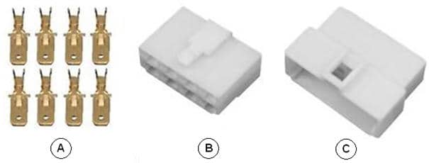
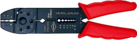
The metal terminals should be crimped onto wires stripped to about 1 mm; the copper wire should not be longer. We insert the end of the wire into the metal terminal and crimp the terminal to the wire using a special AMP-/terminal crimping tool (shown) or a torque wrench.
To make it easier for yourself during connection, you can make a simple drawing with the plug positions 1 to 8 and the lamps/adjustment motor in the headlamp.
In this example, the right turn signal (R) is connected to pin 2, the parking/side light (58R) to pin 5, the adjustment motor to pins 6 and 7, high beam (56a) to pin 7, low beam (56b) to pin 4, and the ground (31) to pin 3.