H-bridge:
A brushed electric motor can be connected to components that need to move back and forth. The electric motor must be able to rotate in two directions so that it can, for example, both open and close a valve.
- To make an electric motor rotate, one of the brushes is connected to a positive terminal and the other to the ground;
- To make the electric motor rotate in the opposite direction, the polarity can be reversed. By swapping the positive and negative, the direction of rotation also changes.
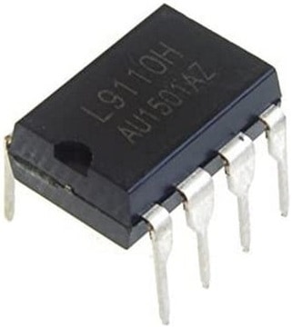
To enable the change of direction of rotation, a so-called H-bridge is used. The ECU controls two transistors or FETs in an H-bridge to provide the electric motor with power and ground. Almost every type of electric motor controlled by an ECU is supplied with voltage and current through an H-bridge. Consider the electric motor of an EGR valve, electronic throttle in a gasoline engine, mirror adjustment, window motor, seat adjustment, steering wheel adjustment, heater valves (mix valve and fresh air quantity valve). The following image shows the H-bridge IC DIL (Dual In Line) with eight pins, type: L9110H.
The diagrams below show an ECU (1) H-bridge (2) with transistors (left) or FETs (right) and an actuator with a potentiometer (3).
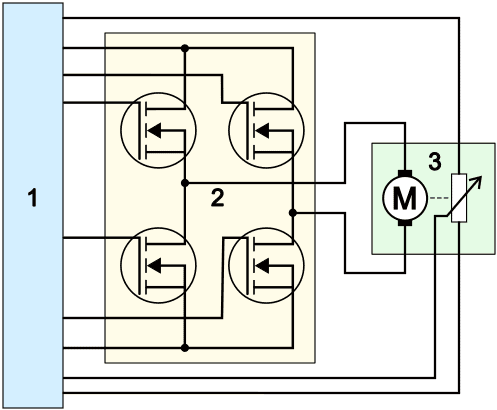
The ECU activates the appropriate transistors or FETs to bring them into conduction. Below, for each type of H-bridge, the two situations are outlined to make the electric motor rotate clockwise or counterclockwise. The top two transistors or FETs switch the positive through, and the bottom two the ground. The green wires are the control wires from the ECU (1) to bring the transistors or FETs in the H-bridge into conduction. The control of both types of H-bridges show many similarities.
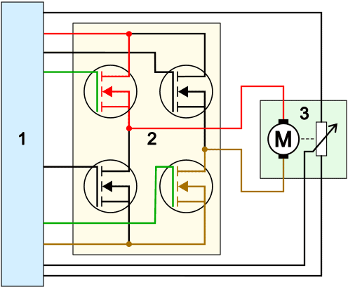
H-bridge with transistors:
- To rotate the electric motor clockwise: the transistors at the top left and bottom right are brought into conduction;
- To rotate the electric motor counterclockwise: the transistors at the top right and bottom left are brought into conduction.�a0
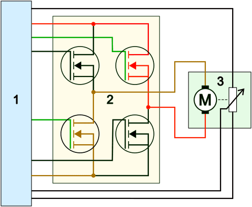
H-bridge with FETs:
- To rotate the electric motor clockwise: the FETs at the top left and bottom right are brought into conduction;
- To rotate the electric motor counterclockwise: the FETs at the top right and bottom left are brought into conduction.�a0
Position Sensor:
The ECU activates the correct transistors or FETs to make the electric motor rotate in the correct direction. In the examples above, a position sensor is also visible next to the electric motor. This position sensor (potentiometer) feeds back the position and direction of rotation of the electric motor to the ECU. Since the ECU thus knows the position of the electric motor, it can move the motor precisely to the position it has been programmed to. An example of this is a heater valve in the heat exchange unit of the fully automatic climate control. The heater valve can be fully opened (100%) or fully closed (0%) but can also be opened to two-thirds (66%). As positions are programmed into the ECU by learning the valve limits, the ECU can drive the electric motor until the potentiometer signal indicates the desired position. The ECU then stops controlling.
Throttle Actuator:
In the first paragraph, the throttle control was mentioned where the H-bridge manages the control of the electric motor. The difference with the previously shown images is the dual potentiometer. In the two images below, we see the dual potentiometers of the throttle actuator.
- Potentiometers with runners facing upwards: both signals progress similarly but at a different voltage level;
- Potentiometers with runners opposing each other: signals are mirrored. When one signal rises upon opening the throttle, the other signal drops.

