Introduction:
A tangle of wires runs through the car. These wires run close to the metal in many places. It is possible for a wire to become damaged and chafed, causing the conductive material to come into contact with the metal of the body. A short circuit may then occur. There are many other reasons why a short circuit may occur, e.g., due to incorrect wiring connections, internal shorts in components, and moisture intrusion in connectors and control units. A fuse of too low a value, or connecting too many consumers to one positive wire, can also lead to a defective fuse.
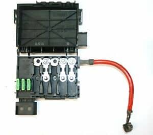
Fuses serve as protection against overload and short circuits. We find fuses in various places in the car. Usually, they are all located in a central spot in the dashboard on the driver and/or passenger side behind the glove box, but sometimes we also find fuses in a plastic holder on the battery or in a fuse box in the trunk.
On this page, we delve deeper into the types of fuses in passenger cars and the ways to detect defective fuses. Diagnosing by measuring the voltage drop across a fuse to determine the amount of current is described on the page: measuring the voltage drop across fuses.
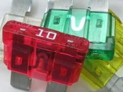
Nominal value:
All fuses have a nominal value, in other words: a maximum allowable current strength; this is indicated on the top of the fuse (e.g., 10 Amperes). This means that a current can flow through of up to 10A. When a higher current than 10A flows through due to overload, an electrical fault, or a short circuit, the conductive contact in the fuse becomes so heated that it eventually melts. The circuit is now broken.
Thus, no more current can flow through that circuit, preventing damage to wires and parts from the short circuit. Before replacing the fuse, the cause must first be known. A fuse does not just break. Here are some causes of a defective fuse:
- An incorrect fuse may have been installed: instead of a 20 A, it has a 10 A;
- There are too many consumers connected to one fuse, e.g., with retrofitted accessories. The fuse, but also the wiring, is not designed for this. So, do not just replace the fuse with one of a higher value, as this increases the risk of overloading the wiring;
- The electrical component behind the fuse has a problem: think of worn/heavy-moving bearings in the interior fan, or a high friction resistance in the window seals, causing the window motor to be heavily loaded. In both cases, this is accompanied by a higher current strength, which perhaps meets the nominal value;
- There is an “intermittent” short circuit, such as two worn wires in a door or trunk seal. When opened and closed, the conductive parts of the two wires come into contact, resulting in a short circuit.
If the fuse continues to fail after it is installed, there may be a short circuit. A test lamp can be used to search for the location of the short circuit. On the page searching for short circuits with the test lamp, it is described how this works.
Types of fuses:
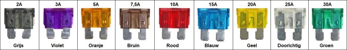
In passenger cars, we usually find blade fuses. Blade fuses come in six different sizes. In the image below, the different fuses are shown. The actual size may differ from the size as depicted below. The legend shows the dimensions in millimeters and the nominal current ratings.
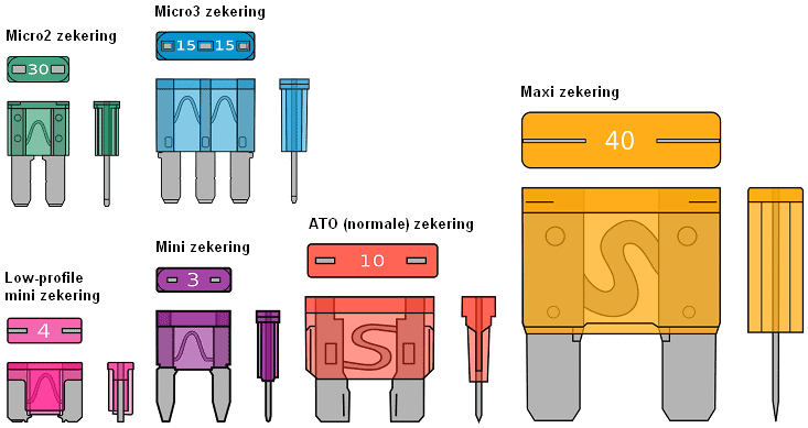
Dimensions (L*W*H):
- Micro2: 9.1 × 3.8 × 15.3 mm
- Micro3: 14.4 × 4.2 × 18.1 mm
- Low-mini: 10.9 x 3.81 x 8.73 mm
- Mini: 10.9 x 3.6 x 16.3 mm,
- Normal: 19.1 x 5.1 x 18.5 mm
- Maxi: 29.2 x 8.5 x 34.3 mm
Current ratings (A):
- Micro2: 5, 7.5, 10, 15, 20, 25, 30
- Micro3: 5, 7.5, 10, 15
- Low-mini: 2, 3, 4, 5, 7.5, 10, 15, 20, 25, 30
- Mini: 2, 3, 4, 5, 7.5, 10, 15, 20, 25, 30
- Normal: 1, 2, 3, 4, 5, 7.5, 10, 15, 20, 25, 30, 35, 40
- Maxi: 15, 20, 30, 40, 50, 60, 70, 80, 100, 120
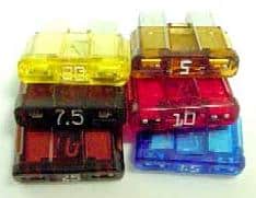
Below are some additional types of fuses that we encounter in passenger cars. Cartridge fuses are mainly found in Japanese and Korean cars, glass fuses are often seen in retrofitted positive cables for amplifiers. Ceramic fuses are commonly found in older cars. High-power fuses may be encountered both in the fuse boxes in the interior and in a box on top of the battery. The high-power fuses are used for, among others, the cooling fan due to the high electrical power.
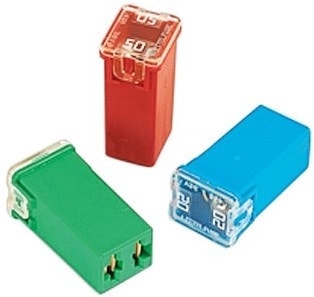
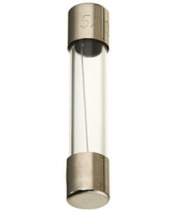


The fuses may look slightly different compared to the image above. Each manufacturer uses, for instance, a different shade of green, and some apply a colored plastic housing over a high-power resistance, while others choose to make the fusible wire visible and stamp the nominal value into the metal.
Checking fuses:
When consumers in the car no longer function, we usually first check the condition of the relevant fuse.
- On the road, one can find in the fuse map (usually applied in the fuse box as in the images below, or on the sticker on the lid, or in the manual) which fuse belongs to which consumer;
- In the workshop, one can find the explanation in the workshop documentation or electrical diagrams (or a combination of both).
Be careful with pulling fuses one by one. Some consumers need to be connected to a power source. During removal, a (harmless) fault may occur, the digital or analog clock on the dashboard may reset, etc. When measurement equipment is available, it is better to detect the defective fuse through measurements rather than optically checking the fuses after pulling them out. This also applies when tracing a parasitic drain, where some pull fuses to see which consumer causes the quiescent current disturbance.
Measurement with the multimeter (1):
With the voltmeter, we can measure the voltage on both conductive sides of the fuse relative to ground. With a fuse in good condition, we will measure nearly the same voltage on both sides. In this case, this voltage is 13.2 volts.
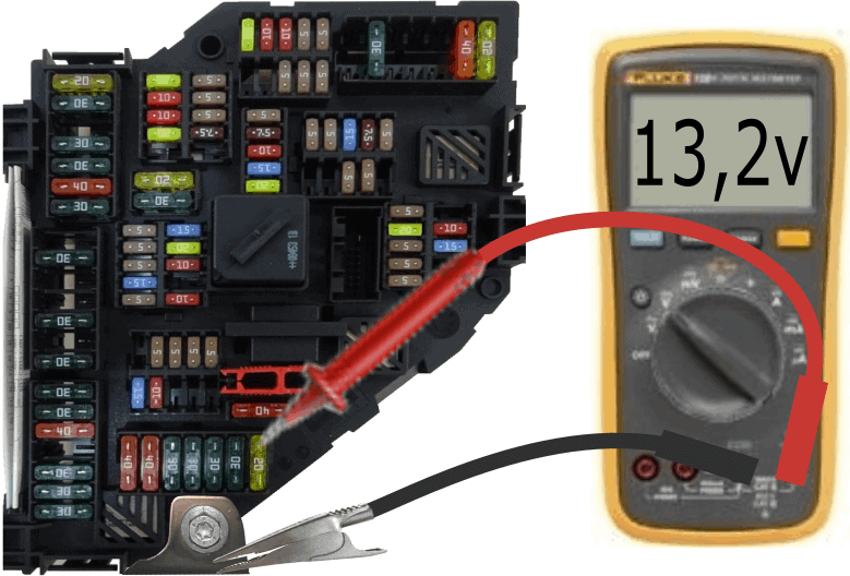
Because the voltage is the same on both sides of the fuse, we know it conducts well. The voltage from the battery’s positive is therefore correctly passed to the consumer.
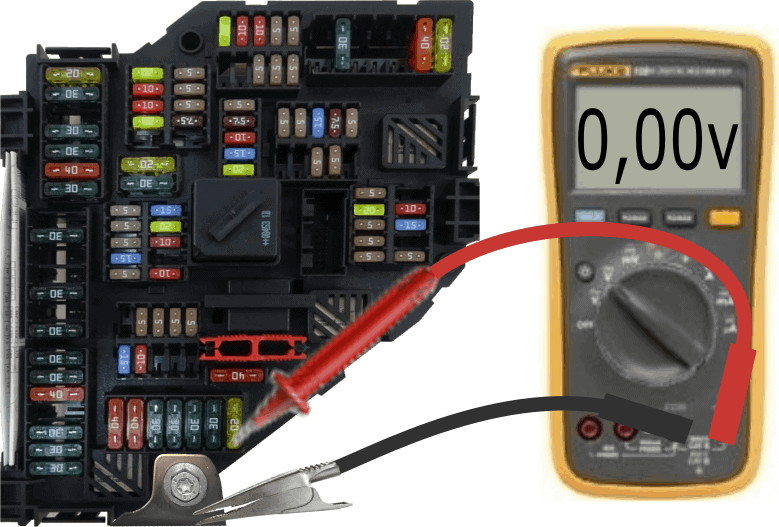
We can also measure the voltage difference across a fuse. When the consumer to which the fuse is connected is turned off, naturally, no current flows. The voltage difference is then 0 volts.
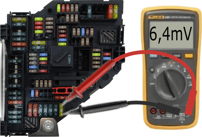
When a consumer is on, current flows from the fuse to the consumer. Due to the (very low) internal resistance of the fuse, a bit of voltage is also absorbed. We lose this voltage, but it is fortunately minimal. In the image, we measure a voltage difference of 6.4 millivolts, which is: 0.0064 volts.
In the table on the page “voltage drop across fuses“, we can find that approximately 2 amperes of current flows through the fuse to the consumer.
This measurement can be handy when searching for a parasitic drain.
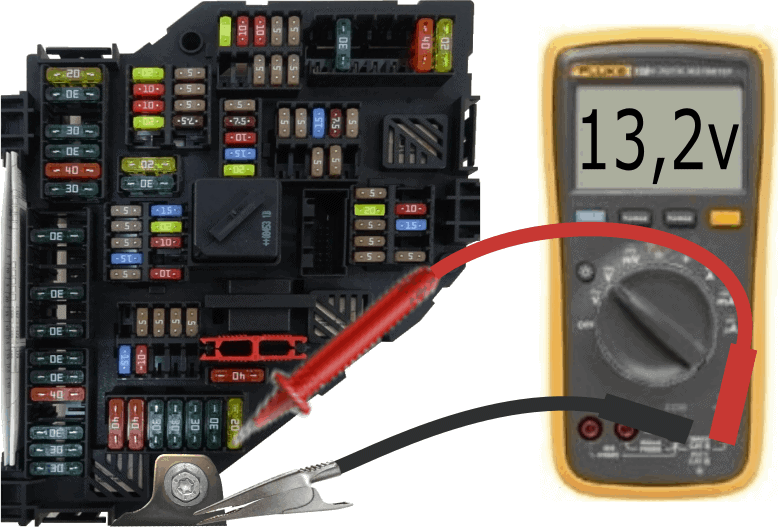
When dealing with a defective fuse, we will measure the board voltage on one side (in the example 13.2 volts) and 0 volts on the other side. The voltage is therefore not passed through the fuse to the consumer. The measurements on the defective fuse are shown in the image below.
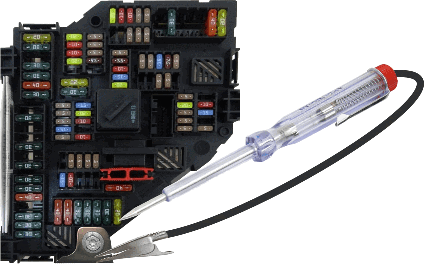
Measurement with the test lamp (2):
A quick way to check fuses is to use a test lamp. The test lamp consists of a pointed end (with which the contact points on the fuse are measured), a housing containing a bulb (tube lamp or LED), and a ground wire with a crocodile clip at the end. We attach the crocodile clip to a good ground point and proceed to check the fuses one by one with the positive side. On all contact surfaces of the fuses that have voltage, the bulb in the housing lights up. In this case, the level of the voltage is not important: either the board voltage (between 11 and 13.8 volts) or 0 volts is present. In the latter case, the test lamp stays off.
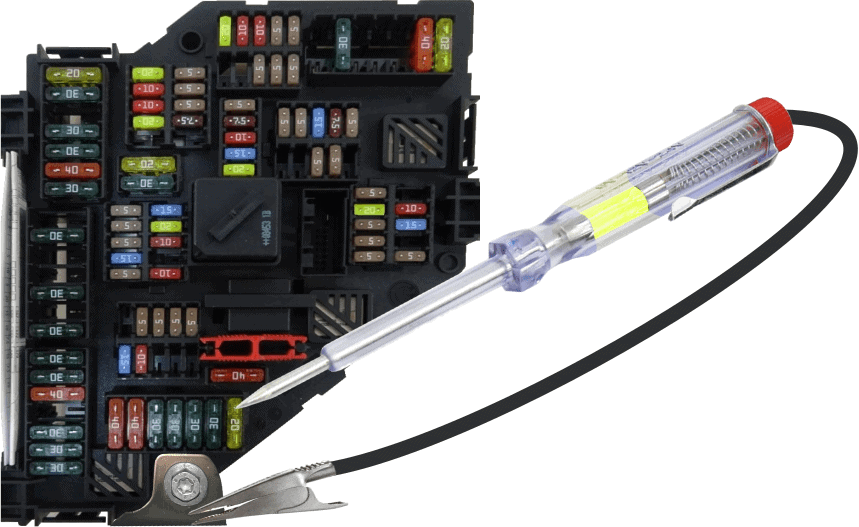
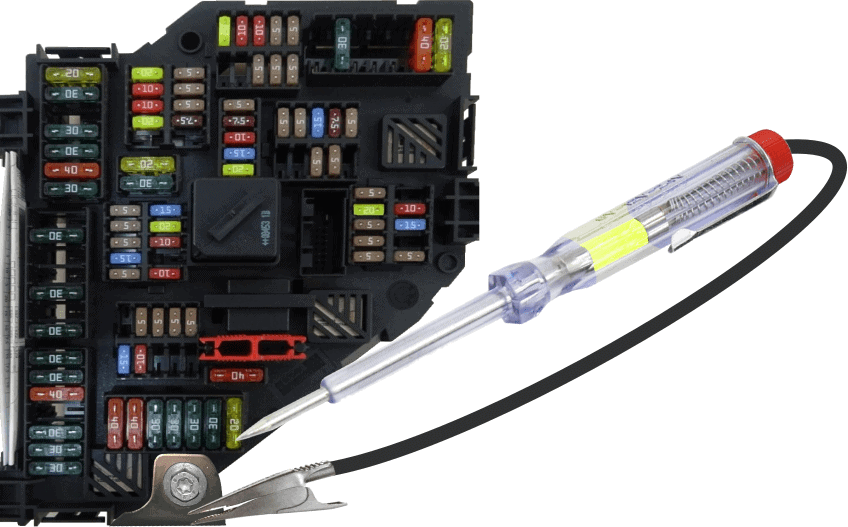
In the following image, we see that the test lamp does not light up. However, it does on the upper contact. This means that this fuse is defective.
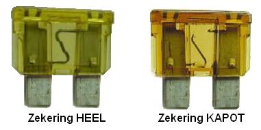
If the test lamp does not light up on either side of the fuse, then there is probably no voltage on the fuse. This can happen if the car’s contact is not turned on, or the consumer is not powered. In the latter case, we can remove the fuse without causing faults and check it optically or with an ohmmeter.
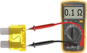
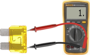
The resistance measurement on a fuse is shown in the two images below. The resistance on a good fuse is about 0.1 Ohms (very low). On a defective fuse, there is no connection between the two measuring leads, and the resistance is infinitely high. The ohmmeter will indicate this as OL or as 1.
Practical situation with a defective fuse:
Anyone who drives, owns, or works on a car may have to deal with it: a fuse that has blown. As previously described, a fuse doesn’t fail for no reason. There is usually something wrong: a short circuit has occurred in an electronic consumer, in the wiring or connectors, or an electrical overload has occurred due to a mechanical problem. In this section, we delve deeper into a practical situation.
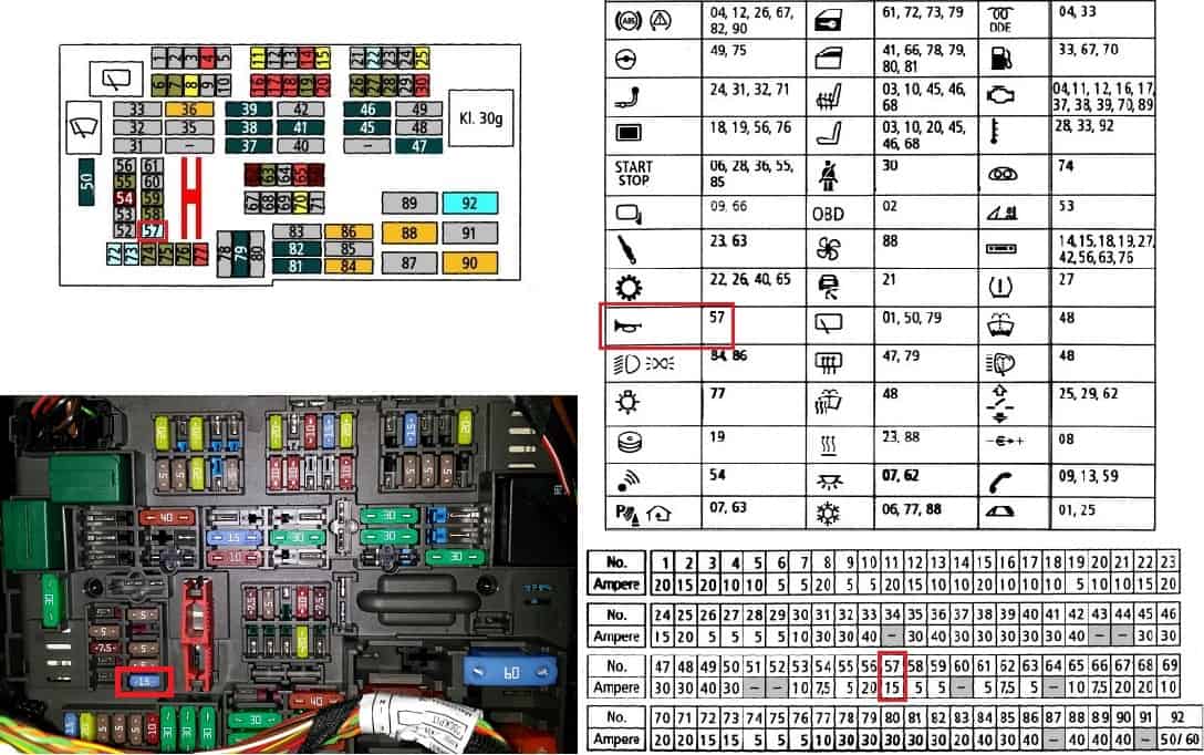
The following problem has occurred: the horn no longer works. When pressing the horn switch (usually the airbag module in the center of the steering wheel or on the turn signal lever), nothing happens. First, we look up the fuse map and position description in the service manual. In the image below, the following is shown:
- top left: positions of the fuses, indicated by a numbering from 1 to 90;
- top right: the components the fuses are for. An explanation of these icons is usually also described on a page;
- bottom right: the nominal fuse values;
- bottom left: a photo of the fuse box.
Since we have a problem with the horn, we look it up in the overview and in the fuse box. The correct fuse is outlined in red. After replacing the correct fuse (of course, with a 15 A fuse), it immediately blows at the moment the horn is operated.
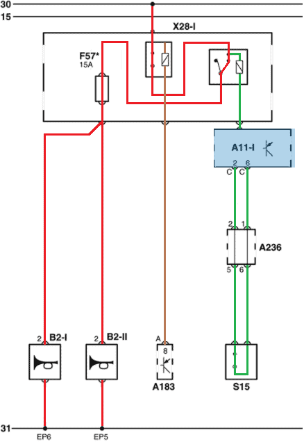
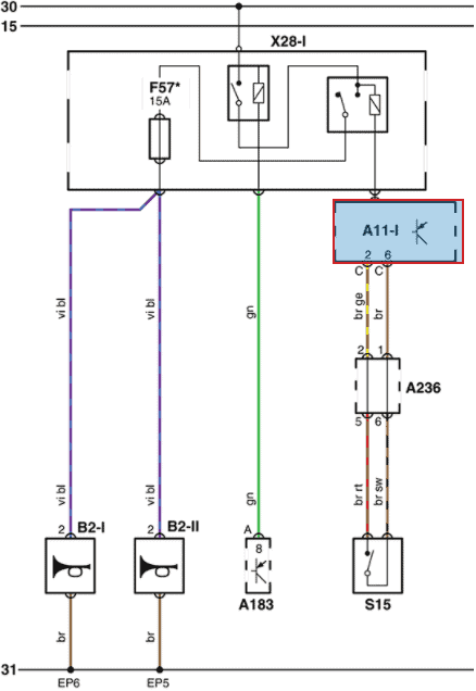
In the workshop, one can consult the electrical diagrams to see how the horns are connected. In the following diagram, we see the horn’s electrical circuit:
- from terminal 30, power (terminal 30) to the horn relay is energized through the ignition switch A183;
- the horn relay (top right) engages as soon as switch S15 closes (this is the horn switch operated by the driver);
- When the horn switch is operated, a current flows through the relay’s coil, and the main current is switched on. The current flows via fuse F57 to both horns (B2-I and B2-II).
Since the fuse immediately blows when the horns are actuated, there is likely a short circuit. By connecting a test lamp over the fuse, we can determine this:
- if the lamp lights dimly when the horns are on, there is a series circuit and not a short;
- a brightly lit test lamp indicates a short circuit: the test lamp gets a direct power and ground and lights at 12 volts, thus at full power.
Visit the page: Locating short circuits with the test lamp for diagnostic explanations.
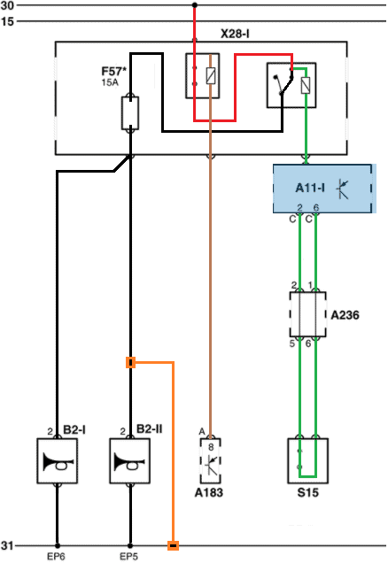
In the following two diagrams, two situations are shown: the current flow in an operating system and with a short circuit.
- with the contact on (via ignition switch A183), the horn relay is powered on pin 30. The horn switch is pressed, and the control current section of the horn relay is energized (green). The main current (red) now finds its way through the relay (output terminal 87) and fuse F57 to the two horns (B2-I and B2-II). The horns are on and emit sound;
- now there is a short circuit. The positive wire of the right horn (B2-II) is connected to ground. There is now a direct connection between the positive (relay output) and ground. To ensure that the current does not reach hundreds of Amperes, which would damage the wiring and components, the fuse interrupts the positive circuit when the 15 A is exceeded.
The short circuit could actually be a chafed positive wire that comes into contact with the car’s body. This can happen after the wiring harness is incorrectly reinstalled in its clips/holders after disassembling work on the bumper and front end. Or after a collision, where the wiring got pinched.