Introduction:
We find electric motors in more and more places in vehicles. In an electric motor, electrical current is converted into motion and heat. Electric motors are used in mirror and seat adjustment, as well as in wiper motors in the windshield wiper mechanism or as a starter motor. These electric motors operate at a voltage of 12 to 14 volts. On this page, we focus on the electric motors in the interior and exterior of the vehicle.
Electric motors also provide the (partially) electric drive in hybrid and fully electric vehicles. This type of electric motor is discussed on the page: HV Electric Motors.
The DC electric motors can be classified into:
- Electric motor with brushes (electromagnetic field and armature)
- Series electric motors;
- Parallel electric motors;
- Brushless electric motors.
Operating Principle of Electric Motors:
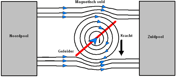
In an electric motor, electrical current is converted into rotary motion. The motion is created as two magnetic poles attract or repel each other:
- A north pole and south pole attract each other;
- Two north poles repel each other;
- Two south poles repel each other.
A magnet has both a north and a south pole with opposite charges. When a magnet is broken in half, you don’t end up with two separate poles, but rather two new magnets, each with a north and a south pole.
Multiple magnetic poles (north and south) are fixed to the housing. Between the north and south pole exists a magnetic field. The output shaft (the armature) rotates due to changes in the magnetic field.
In an electric motor, with the help of usually permanent magnets, or alternatively electromagnets, two like poles are constantly placed opposite each other. Since like poles repel each other, this creates motion.
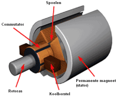
DC Electric Motor with Brushes:
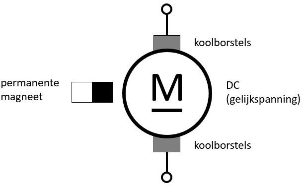
Almost all electric motors in automotive technology are configured as DC motors with permanent magnets and brushes. In these types of electric motors, we find the following magnets:
- Permanent magnets (one north pole and one south pole): between these exists a static magnetic field;
- Coils: in these, an electromagnetic field is induced. In the coils, the rotating electromagnetic field is generated.
The permanent magnets are located left and right of the rotor and consist of one north pole and one south pole. Between this north and south pole exists a static magnetic field that does not change whether the electric motor is in operation or at rest.
In the coils, a rotating electromagnetic field is induced as soon as current flows through it. The current is supplied and withdrawn via the brushes through the commutator.
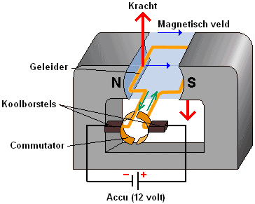
The reversal of current direction is achieved through commutation: two brushes slide over the commutator, which consists of a positive and negative side. The brush on the positive side supplies current to the conductor (green arrows in the image). The current exits the conductor via the brush on the negative side. The current flowing through the conductor causes an electromagnetic field.
Between the resulting magnetism in the armature (the conductor) and the field (the permanent magnets), a force arises (red arrows in the image). This force ensures that the armature and the commutator rotate around their axis. The brushes then touch the other part of the commutator, reversing the current direction in the armature. The magnetic field and force are built up in the same direction, allowing the armature to rotate around its axis again.
We can change the rotation direction of the electric motor (read: the armature) by reversing the positive and negative on the brushes.
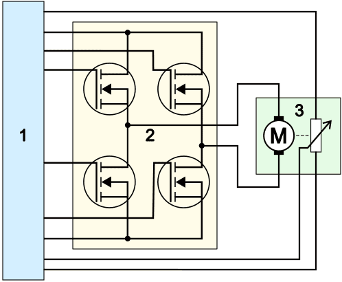
Reversing the positive and negative can be achieved through commutation (as explained above) or can be realized via an H-bridge in an ECU circuit.
- The ECU (1) simultaneously controls two of the four transistors or FETs (4);
- The FETs (2) supply the electric motor (3) with positive and ground. Depending on which two FETs are brought into conduction, the upper brush is positive and the bottom is ground, or vice versa;
- The potentiometer next to the electric motor records the position and rotation direction. Not all electric motors are equipped with a potentiometer.
See the page H-bridge for possible configurations and switching methods of the H-bridge.
DC Electric Motor as Parallel Motor (Shunt) or Series Motor:
Electric motors are used in vehicles in different ways, depending on the requirements for torque, speed, and efficiency. We distinguish two types of DC motors: the parallel motor and the series motor. These are explained below.
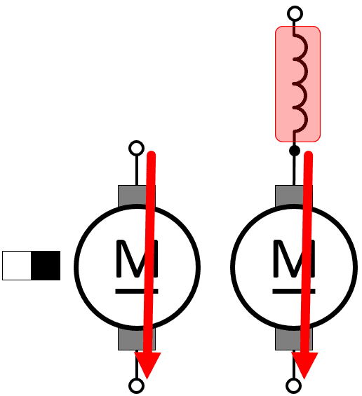
Parallel Motor (Shunt Motor):
In a parallel motor, also known as a shunt motor, the field windings are connected in parallel with the armature winding. This keeps the current through the field winding relatively constant, regardless of the motor’s load. This results in a stable magnetic flux and an almost constant speed, even with varying loads. The force the motor produces is proportional to the current through the armature winding, ensuring smooth operation at different speeds.
A shunt motor is used in systems where controlled speed and prolonged operation are required, such as an electric cooling fan, fuel pump, windshield wiper motor, or electric water pump.
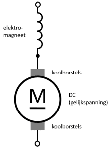
Series Motor:
In a series motor, the field windings are connected in series with the armature winding, causing the same current to flow through both windings. The greater the current through the motor, the stronger the magnetic field becomes. This means that the magnetic flux increases when the load increases, leading to higher torque. This makes a series motor perform exceptionally well under high loads. However, the motor’s speed decreases with increasing load, as the additional magnetic flux increases torque but simultaneously reduces speed.
When engaged, a strong magnetic flux is generated because the current through both the field and armature windings is high. It delivers high startup torque. This makes the series motor very suitable as a starter motor, especially under challenging conditions, such as a cold engine or low battery voltage. Other applications of series motors include electric winches and powering forklifts.
A series motor has a higher starting torque than a parallel motor for the following reasons:
- the starting torque is immediately high when the electric motor is at a standstill;
- no back EMF is generated at standstill,
- current strength is at its maximum at the moment of activation.
The starting torque of a parallel motor (shunt) and series motor can be compared. The formula for calculating the starting torque of an electric motor is:
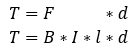
T = torque [Nm]
F = Lorentz force [N]
B = magnetic flux in Tesla [wb/m2]
I = current [Ampere]
l = length of copper wire [m]
d = armature diameter [m]
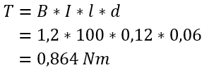
To fill in actual values into the formula T = B * I * l * d, we can make assumptions based on typical values for shunt and series motors in vehicles. A series motor initially has a higher current (I) and thereby a higher magnetic flux (B) than a parallel motor. When other data (length of the copper wire and diameter of the armature) are equal to each other, we can compare the generated torque between the two motors.
First, the table shows the properties of both motors.
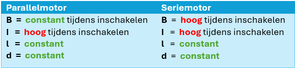
The table above shows that the I (current) is high for both motors, but the B (magnetic flux) is high for the series motor during engagement while it remains constant for the parallel motor.
If we reason this out in a formula, using a 1 for constant and a 2 for high, we see that the generated torque of the series motor is higher:
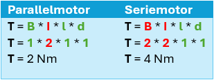
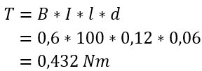
If you prefer calculating with numbers instead of reasoning with 1 or 2 for constant or high, you can view the filled-out formulas below, comparing the parallel and series motors. In this case, the magnetic flux (B) and the starting current (I) are variables, and l and d are equal to each other. The torque of the series motor is also significantly higher in this case.
DC Electric Motor without Brushes:
The brushless DC (direct current) motor is a synchronous motor. The electrical control has replaced the brushes. This type of electric motor is very similar to the synchronous AC motor with permanent magnets, as used in the drivetrain of electric vehicles. The main difference between the two motors is the control: the AC motor is controlled with a modulated sinusoidal AC voltage, and the DC motor with a block voltage.
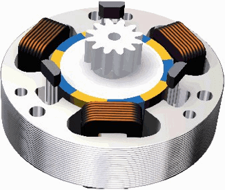
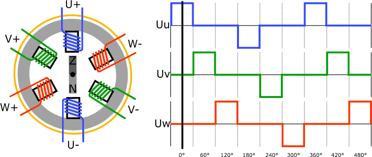
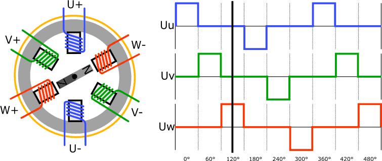
The stator often contains three or six coils (U, V, and W) and the rotor is a permanent magnet. The image below shows the schematic structure of the DC motor along with the voltage pattern through the three coils. In reality, multiple Hall sensors are placed between the poles to determine the rotor position.
The control unit determines which coils to activate based on the rotor position.
In the following image, the U+ coil is energized. The way the coil is wound around the pole determines whether it becomes a north or south pole. In this example, U+ is the north pole and U- is the south pole.
The rotor is configured as a permanent magnet. As described in the previous sections, the rotor positions or rotates due to a changing magnetic field through the coils.
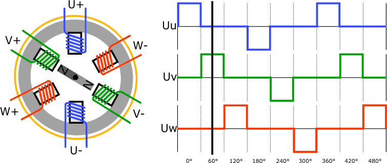
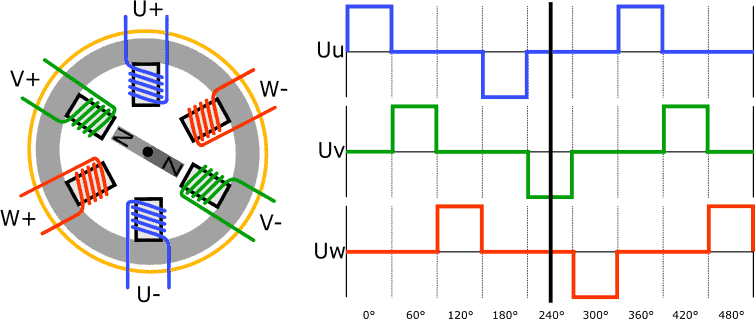
To rotate the rotor counterclockwise from the position shown in the previous image, the V coils are energized.
V+ becomes the north pole, V- the south pole. The rotor with permanent magnet rotates;
the north and south poles attract each other, as do the south and north poles on the other side of the magnet.
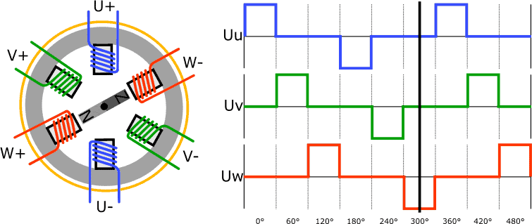
Now the W coils are powered to rotate the rotor another 60 degrees.
The W+ coil becomes a north pole and W- the south pole. The rotor rotates and takes its new position.
The rotor in the next image has rotated 180 degrees since the first situation; in the first image, the south pole was facing upwards; now it’s the north pole.
The polarity of the U+ coil and the U- coil has been reversed, causing the current to flow in the opposite direction through the coils. Thus, the U+ has become a south pole, and the U- a north pole.
The rotor with the permanent magnet is further rotated by the change in magnetic field.

To rotate the rotor another 60 degrees, the V- is made a north pole and the V+ a south pole. The rotor assumes the new position.
Again, the rotor rotates 60 degrees due to changes in the magnetic field in the coils:
The W- coil is the north pole and the W+ the south pole.
In the six situations described above, two coils are constantly energized simultaneously. We often also find brushless DC motors with three coils instead of six. With three coils, the U- V- and W-coils are also energized sequentially, but there is no change in polarity.
The brushless DC motor is a powerful motor suitable for applications where high torque is needed for both starting, medium speed, and high speeds. The brushless DC motor and the stepper motor are often confused. This is understandable because the operation and control of the motors have many similarities: both motors are driven by creating a magnetic field between the coils and the rotor with permanent magnets. However, both motors have significant differences in implementation and material choice, despite the terminology similarities.
The stepper motor is essentially a brushless DC motor, but is used in a different area. While the DC motor is mainly used for prolonged running at high speeds, the stepper motor is used in applications where an adjustment in a precise position is crucial.
The control of the shown DC motor occurs every 60° rotation of the rotor. It could potentially be reduced to 30° if we energize four coils simultaneously between each control, thus achieving an intermediate position. However, a stepper motor can adjust in steps of up to 1.8° to as fine as 0.9°. This further demonstrates that the stepper motor is suitable for very accurate positions.
The various implementations, ECU control methods, and applications can be found on the stepper motor page.