EBS Power Unit:
EBS stands for “Electronically Controlled Brake System” and is found in truck combinations of motor units and trailers with an air brake system. With the conventional air brake system, the driver operates the pneumatic service brake directly with the foot brake valve. With EBS, in a fault-free situation, there is no direct pneumatic actuation.
The image below shows an overview of the air brake system with EBS. Most components are recognizable from the air brake system extensively covered on other pages of this website. In the unit below the brake pedal is the so-called brake value sensor (7), which registers the pedal stroke with sensors. This can be done by measuring the distance traveled by the brake pedal using distance sensors (Knorr) or by potentiometers (Wabco). The pedal stroke is transmitted to the EBS computer (20) via sensors. The EBS computer uses the CAN bus to control the front axle modulator (8) and the rear axle modulator (12) to allow the desired brake pressure to the brake boosters. On the front axle, we find separate ABS solenoid valves (9), which are built into the rear axle modulator. The EBS computer sends the brake signal via the connector (20) to the trailer or semitrailer.
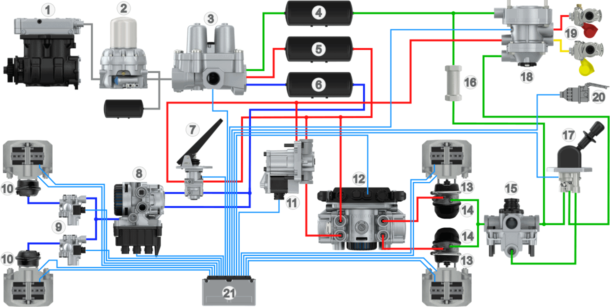
Legend:
- Compressor
- Drier
- Four-Circuit Protection Valve
- Air Reservoir Circuit 3
- Air Reservoir Circuit 1
- Air Reservoir Circuit 2
- Foot Brake Valve / Brake Value Sensor
- Front Axle Modulator
- ABS Valves
- Diaphragm Cylinders (Front)
- Redundancy Valve
- Rear Axle Modulator
- Diaphragm Cylinders (Rear)
- Spring Brake Cylinders
- Relay Valve
- Check Valve
- Parking Brake Valve
- Trailer Control Valve (ECE Valve)
- Coupling Heads (Red = Supply, Yellow = Control)
- Trailer Plug
- EBS Computer
The brake pressure to the diaphragm cylinders depends on:
- The pedal stroke and thereby the deceleration request: The EBS computer calculates the desired deceleration based on the pedal stroke, controlling the modulators of the front, rear axle, and the trailer with the calculated brake pressure. This allows the correct air pressure to be sent to the brake boosters with very fast response times. In the modulators, the pneumatic brake pressure can be held, increased, and decreased. Trucks with an EBS system can brake hard with little pedal force;
- The harmonization, i.e., brake balance: The electronic control of the EBS ECU and the front and rear axle modulators ensure good harmonization between the power unit and the trailer. The delivered brake pressure can be individually regulated for each line;
- The load: Because the modulators regulate the pneumatic brake pressure, an ALR on the power unit is unnecessary. The bellows pressure is measured by pressure sensors in the modulator.
- The brake lining wear: When brake pads wear only minimally, glazing may occur due to aging. To gradually wear the brakes, the brakes can be controlled more or less per axle.
Modern vehicles can be equipped with an automatic braking system, such as in active cruise control or collision detection to prevent a collision. Because the modulators electrically control the pneumatic brakes, braking interventions can take place without the driver.
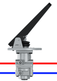
Foot Brake Valve with Brake Value Sensor:
The foot brake valve consists of an electrical and a pneumatic section.
- Electrical: Sensors measure the pedal stroke and thereby the desired braking deceleration of the driver. Wabco uses switches and distance sensors, where the switches register the pressing of the pedal, and the distance sensors measure the piston stroke caused by pressing the brake pedal. Knorr uses potentiometers to determine the position. Just like with the accelerator pedal, the signals from two potentiometers are compared to measure the exact position;
- Pneumatic: When a fault is detected, and the electrical braking system fails, or is deemed unreliable by the EBS ECU, the pneumatic system is engaged as a backup. In this case, the driver must apply more force to the brake pedal. The operation of the pneumatic section is described on the page: service brake.
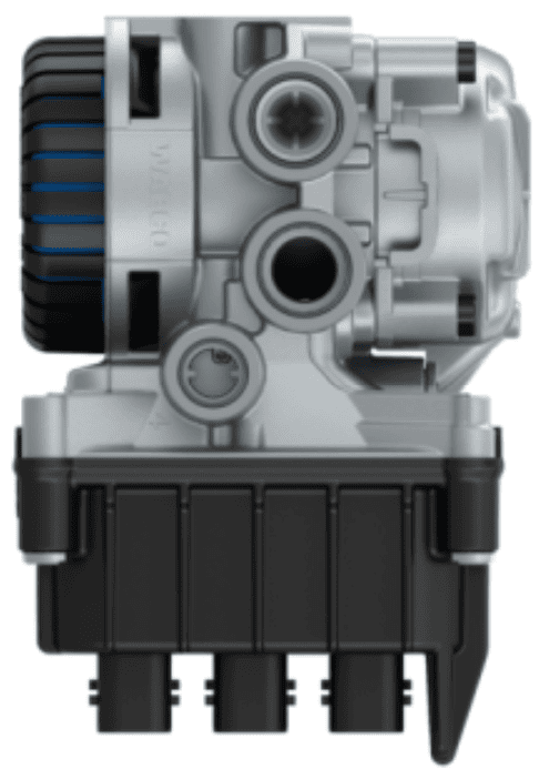
Front Axle Modulator:
The front axle modulator receives the electrical brake signal from the EBS computer and converts this signal into the desired brake pressure. The opening between the air pressure in the tank is allowed to pass to the ABS valve, and thus to the diaphragm cylinder. The electrical signal from the ECU determines how the modulator transmits the brake pressure. This makes the front axle modulator an electrically controlled relay valve.
The ABS valve is shown in the image as a separate component. This is applied at Wabco, among others. At Knorr, we see two front axle modulators with built-in ABS valves.
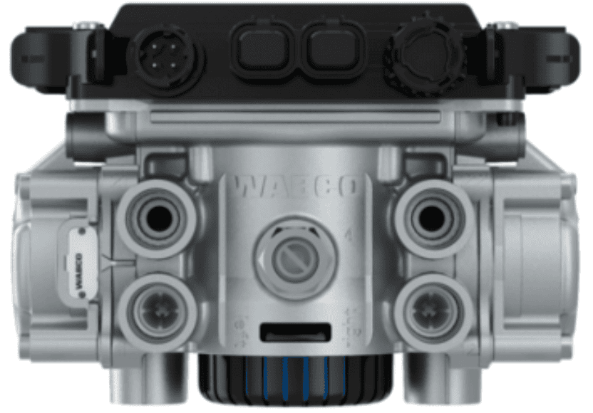
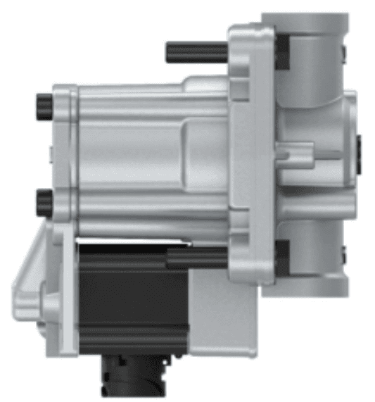
Rear Axle Modulator:
Like the front axle modulator, the desired brake deceleration is sent by the EBS computer to the rear axle modulator to direct the desired brake pressure to the diaphragm cylinders. The ABS valves are integrated into the rear axle modulator.
The ALR (load-dependent brake valve) that we encounter in conventional pneumatic brake systems is no longer present in the EBS system. Instead of the ALR, the bellows pressure is measured by pressure sensors in the rear axle modulator. To make this possible, air lines are located between the air bellows and the rear axle modulator.
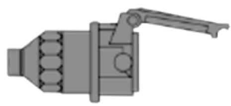
Redundancy Valve:
The redundancy valve acts as a relay valve and is used by Wabco as a backup to enable safe braking of the vehicle under all circumstances. Under normal conditions, the EBS computer controls the redundancy valve, disconnecting the link between the foot brake valve and the rear axle modulator.
In the event of an electrical failure, the redundancy valve ensures that the brake pressure to the brake cylinders is limited so that the vehicle can continue to brake safely. This is achieved by the valve automatically switching to an emergency mode in which it directs the air pressure directly from the foot brake valve to the brake cylinders of the rear axle.
ABS/EBS-ECU:
The ABS/EBS-ECU processes sensor signals from, among others, the brake value sensor, wheel speed sensors, and the status of all connected actuators. With this information, the desired brake pressure is calculated and sent to the modulators of the front axle, rear axle, and trailer to transmit the brake pressure to the brake cylinders. In the case of slipping or locking wheels, the ABS valves are actuated to reduce, hold, or increase the brake pressure.
ABS/EBS Connector:
On the power unit, there is an ABS/EBS connector where the trailer cable can be connected. Once connected, the EBS computer in the power unit can control the trailer modulator for electrical braking. In the event of a fault, the trailer receives brake pressure via the control line (yellow coupling head) to brake it according to the conventional method.
EBS Trailer:
The trailer modulator (8) has an integrated ECU and receives data from the power unit via CAN bus communication through the connector (1). The supply (2) and control couplings (3) are identical to those of the conventional air brake system. When the plug is not connected or a fault occurs, the braking system operates according to conventional actuation, as described on the page: trailer brake system. The ABS system will still function in that case.
The trailer modulator measures, just like the rear axle modulator of the power unit, the bellows pressure to determine the load. This adjusts the brake pressure to the diaphragm cylinders according to the load.
The image below shows the component overview of the EBS system of the trailer.
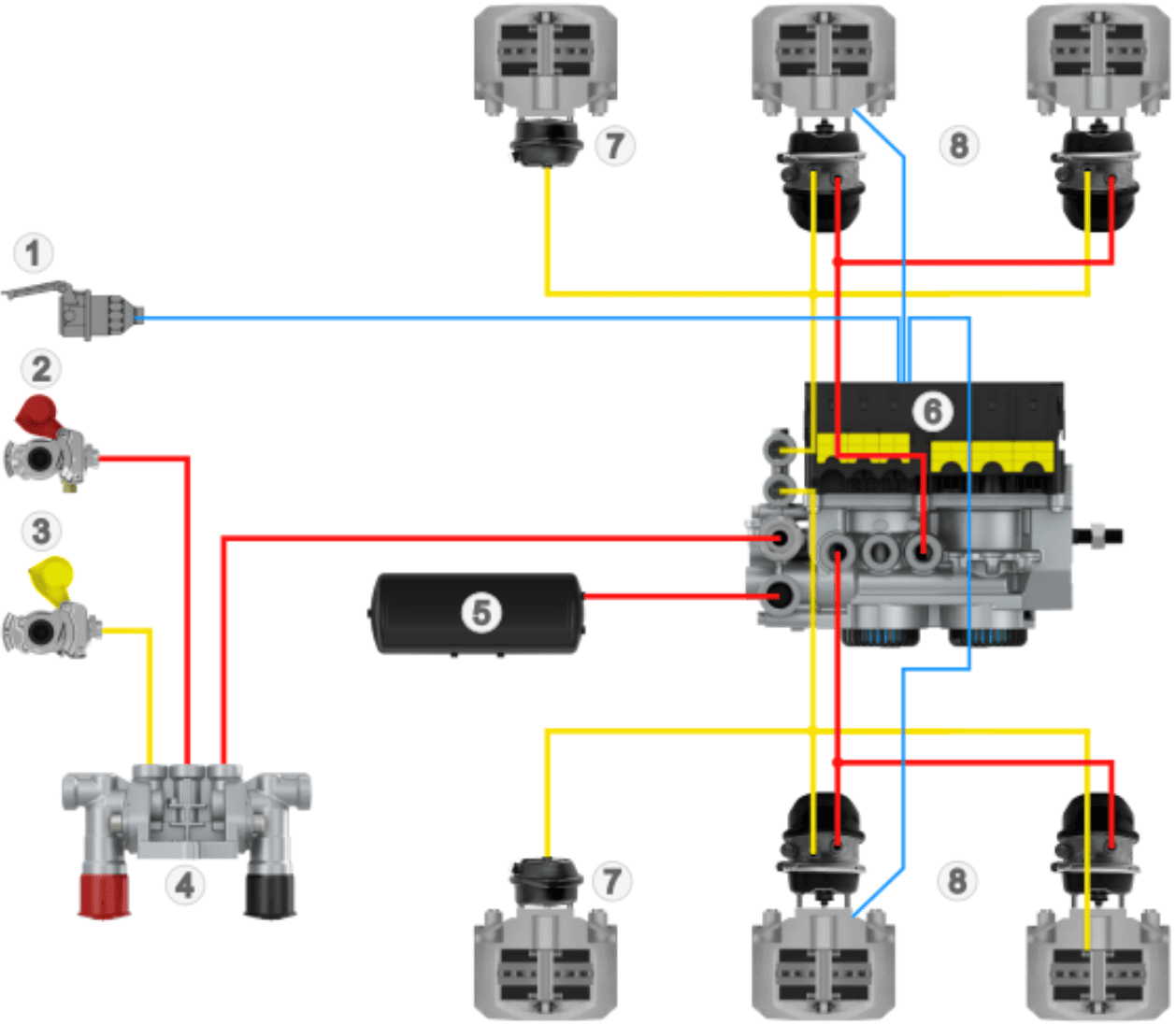
Legend:
- ABS/EBS Connector
- Supply Coupling Head
- Control Coupling Head
- PREV (Park Release Emergency Valve)
- Air Reservoir
- Trailer Modulator
- Diaphragm Cylinders
- Combined Diaphragm and Spring Brake Cylinders
Related page: