Introduction to Disc Brakes:
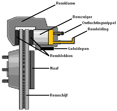
The disc of the disc brake is mounted between the hub and the wheel rim. Thus, the rotor always spins with the wheel. Brake pads are placed on both sides of the rotor. When braking, the brake linings are pushed against the rotor, reducing its rotational speed. The friction between the brake lining and the rotor generates heat.
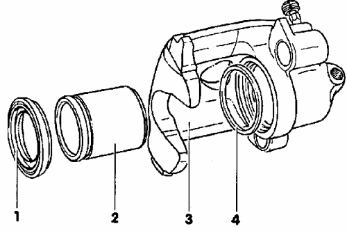
The image shows an overview of the disc brake. When braking occurs, brake fluid is pushed through the brake line into the large (indicated in yellow) area behind the brake piston. Since brake fluid is incompressible, pressure builds up, causing the brake piston to move outward. At this moment, the brake pad is pressed against the rotor.
The brake caliper in the image is of the “floating type.” This means the caliper can slide back and forth over guide pins, as only one piston is present. The next paragraph describes the differences between a floating and a fixed caliper.
Types of Disc Brakes:
Disc brakes can come with either a floating or a fixed caliper. This section describes the functioning of both types.
Disc Brake with Floating Caliper:
In a floating caliper, the brake operates with a single piston. When braking, the piston first pushes the inner brake pad (on the piston side) against the rotor. This causes the caliper to shift to the right. This is possible due to the two guide pins on which the caliper can slide. As the caliper moves over the guide pin during braking, the outer brake pad is also pushed against the rotor. The downside of a floating caliper is that the inner brake pad often wears out faster than the outer one, because the outer pad is often pressed against the rotor with slightly less force. Therefore, it is always very important to especially check the inner brake pad during an inspection. Where the outer pad is 5 mm, the inner pad might be 3 mm.
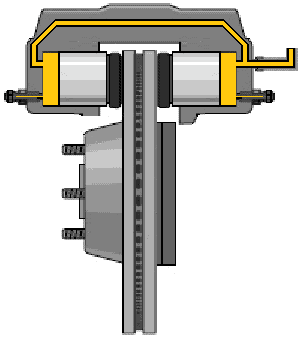
Disc Brake with Fixed Caliper:
In this construction, two pistons are located in the caliper, one on each side of the rotor. The caliper is mounted on the spindle and does not move during braking, unlike the floating caliper. When the brake pedal is pressed, the brake fluid pushes against both pistons. The advantage of this system is that both brake pads are pressed against the rotor with the same force.
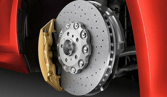
Carbon Ceramic Brakes:
With conventional rotors, the temperature can rise significantly during prolonged, powerful braking. This can result in brake fade, reducing brake performance. This is particularly troublesome in racing and sports cars.
For this reason, automakers have increasingly adopted carbon ceramic brakes since 2000. While the temperature of carbon ceramic rotors also becomes very high (up to 1350°C), their friction properties remain stable at high temperatures. Thus, no brake fade occurs at high temperatures.
Braking performance is optimal when the brakes are warmed up.
The material of these rotors is very hard. As a result, the rotors last much longer than conventional rotors. However, care must be taken during installation or removal of parts such as wheels; striking the rotor with the wheel can easily cause damage.
Another advantage of carbon ceramic rotors over conventional rotors is their low weight. A carbon ceramic rotor weighs up to 70% less than a “normal” rotor. This benefits the unsprung mass, which should be kept as low as possible for optimal vehicle handling.
The downside of this type of rotor is the price; the additional cost of ceramic brakes on a new car can be more than ten thousand euros.
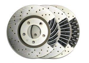
Ventilated and Drilled Rotors:
The image shows rotors that are both ventilated and drilled. The openings in the rotors allow air to flow through, helping the rotors to cool down faster after braking.
Release of Brake Pads:
When braking is stopped, the brake pads must release from the rotor. A rubber ring (number 4 in the image below) is placed around the piston, ensuring the seal between the piston and the brake cylinder. During braking, the ring deforms. Upon releasing the brake pedal, the rubber ring returns to its original shape, slightly retracting the piston and releasing the pads from the rotor. In this design, there is almost always some clearance between the brake pad and rotor. As the pads wear, the piston slides within the rubber ring.
The dust boot is indicated by number 1. The dust boot prevents moisture and dirt from entering the caliper and prevents brake fluid from leaking out.
Measuring Rotor Thickness:
Rotors always wear out with use and last for one or two sets of pads. Rotors become thinner as they wear. Automakers set a threshold for rotor wear, specified in the vehicle documentation as “minimum rotor thickness.”
A special rotor thickness caliper can determine the thickness of the rotors. Measuring rotor thickness cannot be done with a normal caliper, as a normal caliper has flat jaws that measure the thickness of the (rust) rims on the rotor. This is not desirable, as only the thickness where the pads contact the rotor is of interest. A rotor thickness caliper measures the contact surface where the brake pad meets the rotor. This is shown in the image below and explained further underneath.
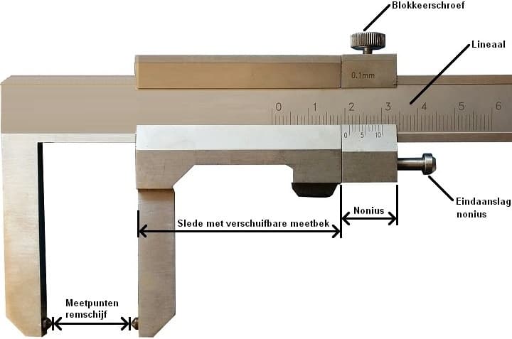
Between the two caliper jaws are tabs placed against the tread of the rotors, i.e., the areas where the pads touch the rotors. The tabs protrude so that the thicker (rust) edge of the rotor does not interfere with the measurement. To maneuver the caliper over the rust rim, the vernier (later readout) can be adjusted. During measurement, the locking screw should be tightened so that the vernier can no longer move.
The image shows such a caliper.
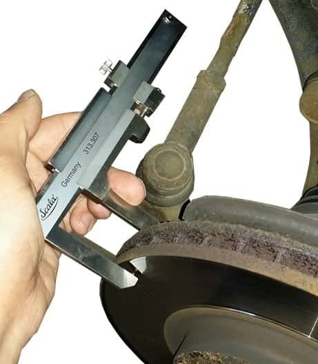
When measuring, the jaw tabs must be pressed against the rotor (see image below). The vernier must be moved to the end stop, fully to the right, until it can no longer move. The locking screw should then be tightened so that the vernier cannot slide back and forth across the ruler. At this point, the caliper can be removed from the rotor. The caliper jaws can be moved to slide over the (rust) edge because the vernier is locked in its furthest position. The position of the jaws does not affect the indicated vernier value on the ruler.
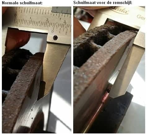
Once the caliper is removed, the vernier and ruler can be read. The image below shows a magnified view of the measurement of the rotor measured above. The indicated size is 21.2 mm.
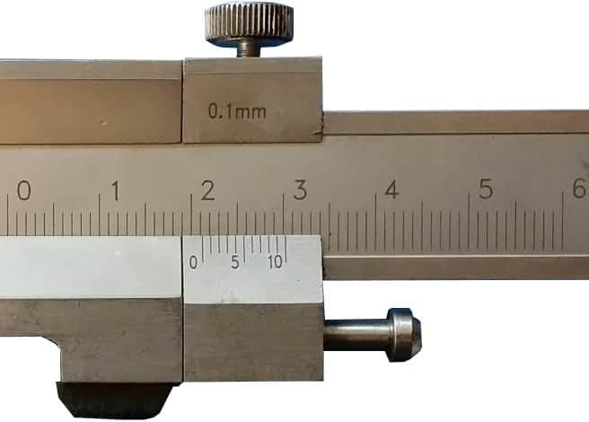
In the vehicle where the rotor was measured, the minimum rotor thickness is 22.0 mm. The measured value, 21.2 mm, is thus lower than the minimum value. Therefore, the rotors need to be replaced. If the measured value were higher than the minimum rotor thickness, the rotors would still be thick enough to install a new set of pads.
Brief explanation on reading the caliper:
The ruler has a long line to the left of the 2. This is the 2 cm line, or 20 mm.
The 0 of the vernier is slightly past the 21 mm. This means the size is a bit larger than 21 mm, so a decimal will follow. To determine the decimal, look for the line where the ruler and vernier align. It is the second line (counting from the 0), so the exact measured size is 21.2 mm.
More detailed explanation of mechanical measurement tools is available on the mechanical measurement tools page.
Warped Rotor:
When the driver brakes hard, parts of the braking system become very hot. During prolonged braking, rotors can reach temperatures exceeding 300°C. If the driver holds the brake pedal down while the car is stationary, the pads press against a stationary rotor. The rotor will cool unevenly, meaning that while the entire surface cools, cooling does not occur where the pads contact the rotor.
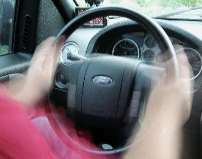
Due to the temperature difference, the rotor can slightly deform, becoming “warped.” The steering wheel might vibrate when the brake pedal is engaged. The vibration can be felt throughout the vehicle in severe cases.
Another way warped rotors can occur is if the vehicle drives through water puddles after a long braking period. Water hitting the rotor can cause uneven cooling, potentially causing the rotor to warp.
The next section describes how to measure rotor runout.
Measuring Rotor Runout:
If the car’s steering wheel vibrates during braking, warped rotors may be present. The vibration is often noticeable even at low vehicle speeds. To ensure that the vibration is not caused by other suspension components, the rotor’s runout can be measured.
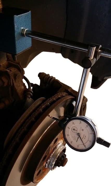
To measure rotor runout, a fixture with a magnet is mounted on a fixed part of the vehicle (e.g., the shock absorber). At the fixture’s end, a dial indicator is mounted, with the needle placed against the rotor. This is shown in the image below.
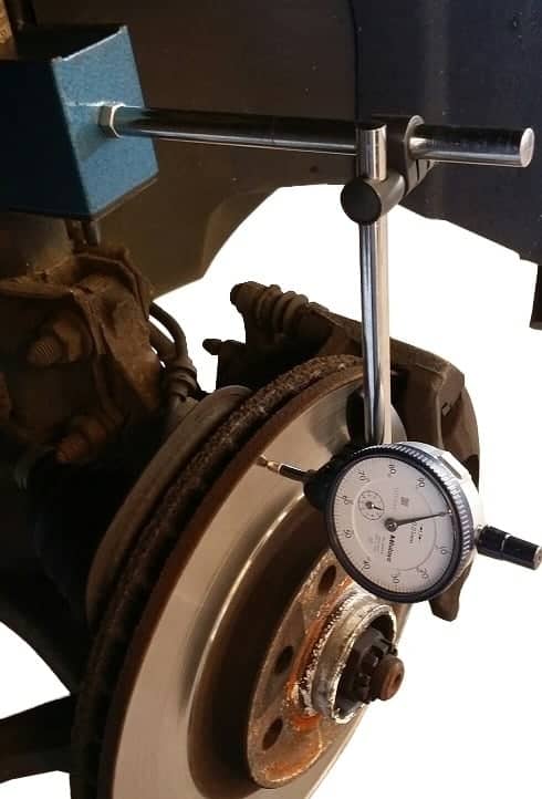
After setting the gauge to 0 and securely mounting the fixture, the rotor can be rotated. The dial indicator needle will show how far the rotor moves inwards and outwards. The image below shows a point where the dial indicates 20. This 20 represents 0.20 mm. Factory data for this vehicle specifies the maximum permissible rotor runout as 0.1 mm. In this case, the runout is 0.1 mm more than allowed, indicating a warped rotor.
Sometimes, the wheel hub itself may also be warped. To ensure that only the rotors cause the vibration, the rotor can be removed from the hub, and the same measurement can be performed on the hub. If the dial indicator needle moves excessively in that case, the hub, and therefore also the wheel bearing, should be replaced along with the rotor.
Related page: