General Crankcase Ventilation:
Crankcase ventilation is a system that directs vapors from the crankcase to the engine’s intake manifold. In the oil pan, besides engine oil, there is also air. This air mixes with oil vapors and a small amount of combustion gases that pass the piston rings into the crankcase. These are known as “blow-by” gases, and these vapors should not be released into the atmosphere. If done intentionally, as with older engines, it was referred to as Negative Crankcase Ventilation, which is harmful to the environment as the vapors contain combustion residues, steam, and fuel vapor.
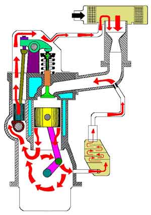
Nowadays, vapors are routed through hoses and pipes back to the engine’s intake system (as shown in the adjacent image). The crankcase vapors are thus drawn in by the engine and take part in the combustion process. Once burned, they no longer pose harm. A completely closed crankcase ventilation system is termed as Positive Crankcase Ventilation, abbreviated as PCV. The positive crankcase ventilation system is equipped with a PCV valve that regulates the pressure to the crankcase.
Crankcase ventilation and crankcase breathing are often confused, but there is a fundamental difference:
- In crankcase ventilation, the crankcase vapors are removed and fresh air is introduced;
- In crankcase breathing, only the crankcase vapors are vented.
Crankcase Ventilation Valve:
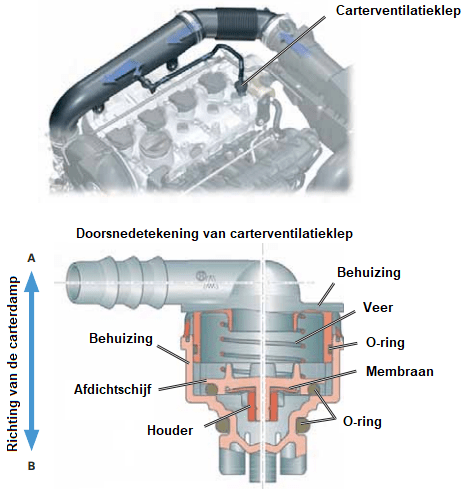
The crankcase ventilation system incorporates both a non-return and a pressure control valve, which vents the overpressure from the crankcase ventilation to the engine’s intake, closing in the opposite direction. Typically, the crankcase ventilation valve is a spring-loaded diaphragm valve maintaining the crankcase vacuum at approximately 0.02 to 0.03 bar relative to atmospheric pressure.
Upon opening the PCV valve, water vapors and blow-by gases are absorbed into the intake air and combusted within the cylinder.
The crankcase ventilation valve connects to the atmosphere on one side and the intake manifold on the other. Its purpose is to maintain a low, constant pressure in the crankcase amidst changing intake manifold pressures.
- At idle speed, the pressure in the intake manifold is low (vacuum). The valve is nearly closed;
- When accelerating, the throttle valve opens slightly, increasing the intake manifold pressure (less vacuum). The valve opens further.
As the valve opens, the sealing disc moves upward against the spring force, enlarging the passage to redirect more crankcase vapors to the intake.
Blow-by Gases:
The gases that escape from the combustion chamber into the crankcase are known as blow-by gases. Blow-by gases can enter the crankcase through various means. Factors such as piston clearance, the condition of the piston rings, and the cylinder wall’s oval shape and wear most significantly impact the quantity of blow-by gases produced by an engine.�a0
During combustion, approximately one kg of water vapor per liter of fuel is produced, a portion of which enters the crankcase via the piston rings.
During the warm-up of a cold engine and with a rich fuel mixture during acceleration, the most blow-by gases are produced, introducing unburned or partially burned fuel into the crankcase. Blow-by gases consist of 10 to 40% oil and the remaining portion includes gases such as H20, CO, CO2, HC, and NOx.�a0
Crankcase Ventilation and Breathing System Types:
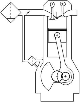
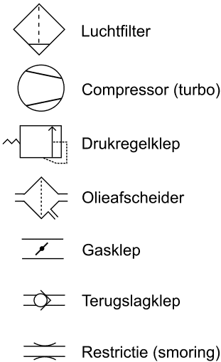
The images show part of the engine block revealing the type of crankcase breathing system in place. The components of the crankcase breathing system are illustrated using pneumatic symbols.
The legend explains the meanings of these symbols.
Each type of crankcase breathing system is numbered (from 1 to 7).
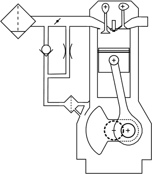
1. unregulated crankcase breathing with discharge before the throttle:
The crankcase breathing system consists of an oil separator and a hose leading to the air tube between the air filter and the throttle valve. This is the simplest type of crankcase breathing system commonly found in passenger cars. Several disadvantages are associated with this construction:
– The crankcase vapors can contaminate the mass air flow sensor;
– The vacuum in the crankcase depends on the air filter resistance.
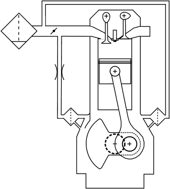
2. crankcase breathing with non-return valve before, and restriction after the throttle:
Compared to number 1 (above), this configuration offers better ventilation due to improved airflow over the throttle under partial load. A downside is the more complex construction compared to number 1.
3. crankcase ventilation with flow direction change in the ventilation line:
The main advantage is that this involves actual ventilation in the crankcase rather than just venting. Downsides include the need for a second oil separator and the reversal of airflow in the oil separator.
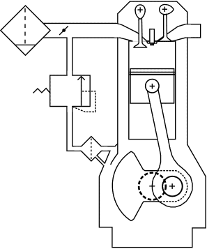
4. regulated crankcase breathing with discharge after the throttle:
Since this configuration is positioned after the throttle, there is more vacuum in the crankcase breathing system (a stronger suction effect). Therefore, a pressure regulator is required. A pressure regulator is located between the oil separator and the intake pipe, opening only at a certain crankcase pressure. Without overpressure in the crankcase, the pressure regulator remains closed.
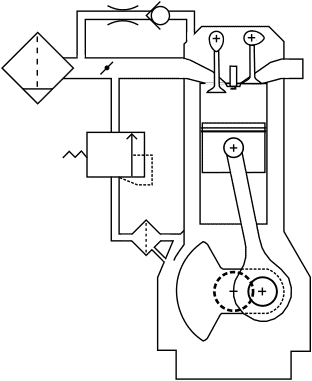
5. regulated crankcase ventilation system with discharge before the throttle:
This setup also includes a pressure regulator. The addition to this system is the hose between the air intake tube before the throttle and the connection on the valve cover, enabling ventilation. The downside is the potential for false air intake over the throttle.�a0
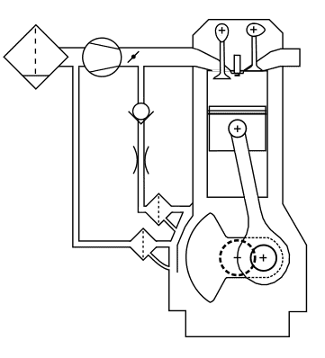
6. unregulated crankcase breathing in a forced induction engine:
A non-return valve in the crankcase breathing hose between the throttle valve and the intake manifold prevents the turbo from blowing overpressure into the crankcase ventilation system. Under full load conditions, this overpressure valve would remain closed, causing the crankcase pressure to rise excessively. Therefore, an extra oil separator with a hose attached to the turbo’s suction side is installed.
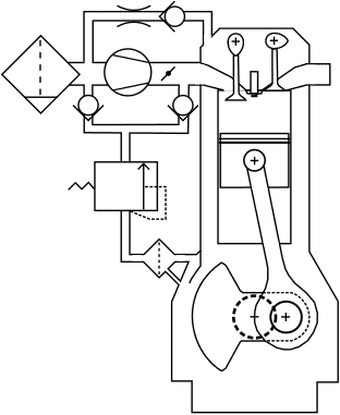
7. regulated crankcase ventilation system in a forced induction engine:
The hose leading to the valve cover enables crankcase ventilation. The pressure control valve with two check valves creates a higher vacuum for the oil separator. However, this system is more complex.
Oil Separators:
To prevent engine oil from being drawn into the intake system via crankcase ventilation along with blow-by gases, manufacturers use oil separators. Without an oil separator, components such as the mass air flow sensor, turbocharger, valves, and the catalytic converter or particulate filter could become contaminated or damaged. As the name suggests, an oil separator separates air and oil residues. Oil separators come in various types: cyclone, labyrinth, and electrostatic oil separators. These three types are described in detail in the following sections.
Cyclone Oil Separator:
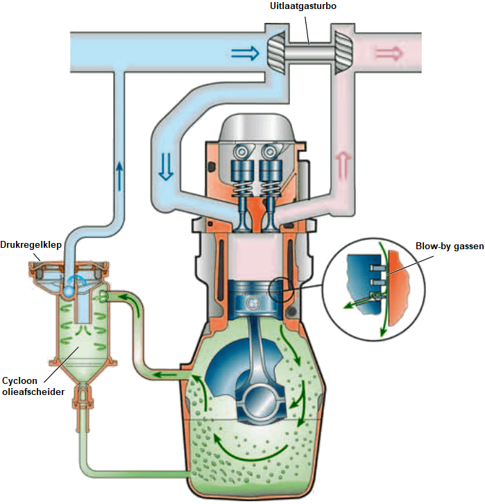
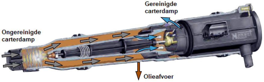
The cyclone oil separator separates oil and air in the crankcase vapors by swirling the air. The centrifugal force generated during swirling throws the heavier oil particles against the inner surface of the housing.
The remaining oil droplets are returned to the crankcase via a hose. The air pushes the pressure control valve upward against the spring force and is directed to the engine intake. The image shows the turbocharger drawing in this air.
The pressure control valve closes when a vacuum threatens to form in the crankcase, for example, when the turbo draws in a lot of air. Excessive vacuum in the crankcase could damage seals and gaskets.
Labyrinth Oil Separator:
A labyrinth oil separator is often combined with a cyclone separator. In the labyrinth oil separator, the crankcase vapors collide with baffles. The oil droplets are separated from the air and fall back into the crankcase. The remaining oil residues are then separated from the vapor in the cyclone separator.
If crankcase pressure increases and excessive crankcase vapors occur, for example, due to excessive wear on piston rings, the pressure relief valve opens to prevent crankcase pressure from rising too high.
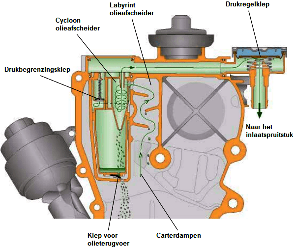
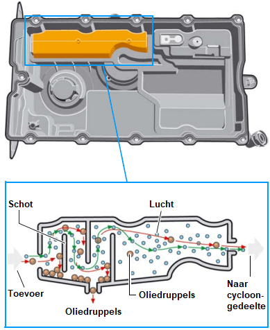
The images below show a valve cover from a 2.0 TDI VW engine. Both types of oil separators are installed in the valve cover.
The images below illustrate the positions of the labyrinth and cyclone oil separators. The crankcase vapor enters the labyrinth (left). In the labyrinth, large oil residues are separated from the passing air. From the labyrinth, the crankcase vapor moves into the cyclone section to remove the last oil residues from the air.

Electrostatic Oil Separator:
The previously mentioned oil separators do not achieve 100% effective separation. If crankcase vapor moves at low speed through these types of oil separators, as can happen at low RPMs, small oil droplets remain in the vapor. The electrostatic oil separator also removes these small droplets from the crankcase vapors. The purified crankcase vapor contains less than one percent of the oil present in the unpurified crankcase vapor.
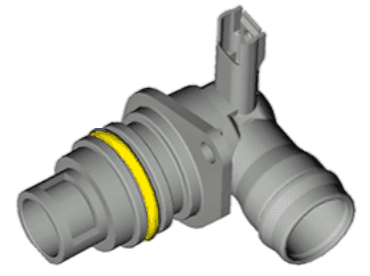
The image below shows the electrostatic oil separator.
Using high voltage, even the smallest oil droplets become magnetically attracted, adhering within the separator. This way, the oil is separated from the air.
Inside the housing, a transformer converts the vehicle’s 12 or 24-volt electrical system (in a passenger or commercial vehicle) to a high voltage of 9 to 12 kilovolts.
Electric Heating for Crankcase Breathing:
Water vapor is present in the crankcase vapor. The “blow-by gases” section describes that approximately one kg of water vapor is released per liter of fuel, with some portion entering the crankcase via the piston rings. With a cold engine where the temperature in the crankcase breathing system is below 70 degrees Celsius, the water vapor will condense as water. Multiple cold starts and short journeys contribute to a significant accumulation of water in the engine block.
As the engine runs, part of the moisture evaporates, and the vapor is expelled through the crankcase breathing system. The crankcase vapors condense on cooler engine parts, including the crankcase vent hoses. To prevent the vapor from freezing in the hose at low outside temperatures, many car manufacturers install one or more heating elements in a crankcase vent hose.
The heater is activated by the ECU during a cold start.
In engines without a heating element, or if the heating fails, there is a risk that the vent hose will freeze, creating a blockage. This significantly increases crankcase pressure. Increased crankcase pressure can cause oil leaks through the crankshaft seal or gaskets (valve cover or oil pan gasket).
In engines that do not reach operating temperature frequently, water in the oil pan may freeze. Since oil floats on water, the ice can block oil flow to the oil strainer. Low oil pressure can cause engine damage. The electric heating described in this section does not solve this issue: it prevents freezing in the crankcase ventilation hoses that are located higher in the engine bay. To avoid excessive water accumulation in the crankcase, it is advisable to allow the engine to warm up properly by taking long trips, adhering to maintenance schedules, and avoiding short trips of a few kilometers whenever possible.
Common Problems with Crankcase Ventilation:
- Clogged crankcase ventilation: High pressure builds up in the crankcase, hindering engine operation. Engines with excessive white sludge (oil residues mixed with moisture, caused by frequent short trips where the engine never reaches temperature, or due to a faulty thermostat) can completely clog the crankcase ventilation. The hoses become filled with sludge and can freeze in winter (as white sludge largely consists of moisture). If this occurs, the hoses can spontaneously burst.
- Cracked hoses: Oil deteriorates rubber. Crankcase vapors contain oil residues, and the hoses to the intake are often rubber. As these hoses age, they can crack. These hoses often feel like gum before cracking, indicating they need replacing.
- A cracked crankcase ventilation hose can cause an unpleasant oil smell in the engine bay and interior. The engine will also draw in false air, leading to extra unmeasured air bypassing the mass air flow sensor. Too much air can cause the engine to run irregularly, consume more fuel, and illuminate the check engine light.
- Engine contamination: Despite the use of oil separators, small oil droplets can still remain in crankcase vapors. This can contaminate the engine’s intake system, including the throttle body and intake valves.
- Increased crankcase pressure: This is not a problem with the crankcase ventilation itself, but it can be observed via the breather. When there is excessive air blowing through the crankcase ventilation, it could be due to one or more damaged (compression) piston rings or cylinder wall. The mixture leaks past the piston rings into the crankcase (blow-by) during compression strokes. To confirm that the piston rings are the cause, a compression test or cylinder leak test should be conducted. In engines experiencing this, engine oil will degrade and foul more quickly due to fuel and combustion gases.