Introduction:
In modern motor vehicles, there are dozens of control units responsible for the operation of both the combustion and electric motors, as well as for comfort and safety functions. These control units are equipped with software that processes the signals from sensors and determines which actuators should be activated based on that information. On the page “Interface Circuits” we delve deeper into the process where the input and output signals are processed by the ECU (control unit).
In the following image, we see the engine management ECU in the center, with sensors on the left and actuators on the right.
- Sensors send a voltage with low current to the ECU. The level of voltage (ranging from 0 to 5 or 14 volts), the frequency (RPM), or the pulse width of a PWM signal provides the ECU with input about the measured value from the sensor.
- With actuators, it’s more about the current strength than the voltage. Although voltage is needed to generate current, the actuator will not operate without this current.
The page “Sensor Types and Signals” delves deeper into the input signals from the sensor to the ECU. This page highlights the control of actuators.
Control of an actuator by a relay, transistor, and FET:
The actuator is switched on and off by the ECU. In the ECU, an electrical connection is made or broken by means of a transistor or a FET.
The control principle of a transistor is similar to that of a relay: both components are controlled with a control current to bring them into conduction. However, the operation of a transistor differs from a relay: the transistor has no moving parts. The transistor switches with an electron current.
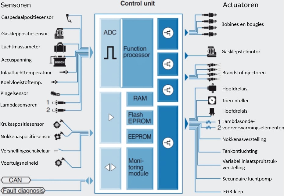
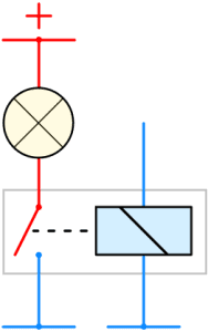
In the three images below, we see a relay circuit with a lamp.
- Relay off: there is no control current. The coil is not magnetic, so the switch in the main current side is open. No main current flows. The lamp is off;
- Relay on: the relay coil receives a supply voltage and is connected to ground. A control current flows and the coil consumes the supply voltage to become magnetic. As a result of the magnetic field, the switch in the main current section is attracted. A main current flows and the lamp lights up;
- Schematic of control current through the coil and main current through the lamp.

In an ECU, transistors and/or FETs are switched on and off. In the following three images, we see a transistor circuit with again a lamp as the consumer. The transistor is of the NPN type.
- Transistor not conducting: no supply voltage is applied to the base connection of the transistor. There is no control current, thus the transistor does not switch any main current;
- Transistor conducting: a supply voltage is applied to the base connection. A control current flows from the base through the emitter to ground. The transistor conducts, thus connecting the ground terminal of the lamp with the ground of the circuit. A main current flows and the lamp turns on;
- Schematic of control current through the transistor and main current through the lamp.
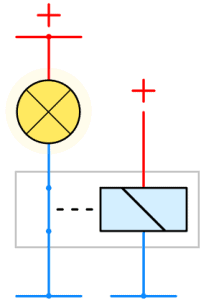
Increasingly, we see FETs being used in ECU applications. FET stands for “Field Effect Transistor.” The main difference between a FET and a transistor is that a FET is brought into conduction with a voltage, while a transistor requires a control current. When the FET is brought into conduction, an electron current starts to flow. The electron current runs from negative to positive (actual current direction).
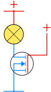
- FET not conducting. The gate is not provided with a control voltage;
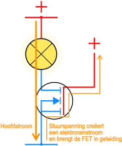
- FET conducting: a control voltage is applied to the gate. The FET conducts, causing a main current to flow through the lamp;
- Schematic showing the direction of the electron flow (from negative to positive) through the FET.
The operation of the transistor and FET is described on separate pages. On this page, we focus solely on the switching principles of actuators.
Control of an actuator by an ECU:
The transistor and FET are mounted on the ECU circuit board, but sometimes also incorporated into actuators. In this section, we delve deeper into the ECU circuits for four different types of actuators. The image shows two passive actuators with their own positive and a ground switch via the ECU.
Passive actuators are – in most cases – equipped with a coil, which has its own supply voltage and is switched to ground by the ECU. A passive actuator may have a position sensor, but it is often also passive (an external potentiometer), and is processed in a different part of the ECU via a separate signal wire.
When the current through the actuator is directly controlled by the transistor in the ECU, it is called a power transistor. The control of a passive actuator can also take place via a FET.
The images below show examples of how passive actuators are controlled.
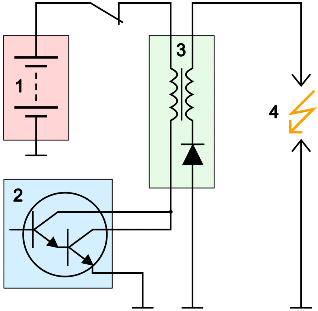
1. Coil control: for a coil without internal drivers, the primary current of the coil is switched to ground by the ECU. The image shows the power transistor in the ECU (2), implemented as a Darlington configuration to provide a greater amplification factor, which grounds the primary coil of the coil (3) to charge the primary coil. The secondary coil is connected to the spark plug side (4).
2. Electric motor control: using an H-bridge, a brushed electric motor can rotate in two directions. The H-bridge can be implemented with transistors or FETs as shown. The electric motor is equipped with a potentiometer to feedback the position to the ECU. Applications can include: blower flap motor, EGR valve, mirror glass, seat adjustment, throttle valve. In the latter case, a dual potentiometer is used for safety. The H-bridge is usually an IC mounted on the ECU circuit board.
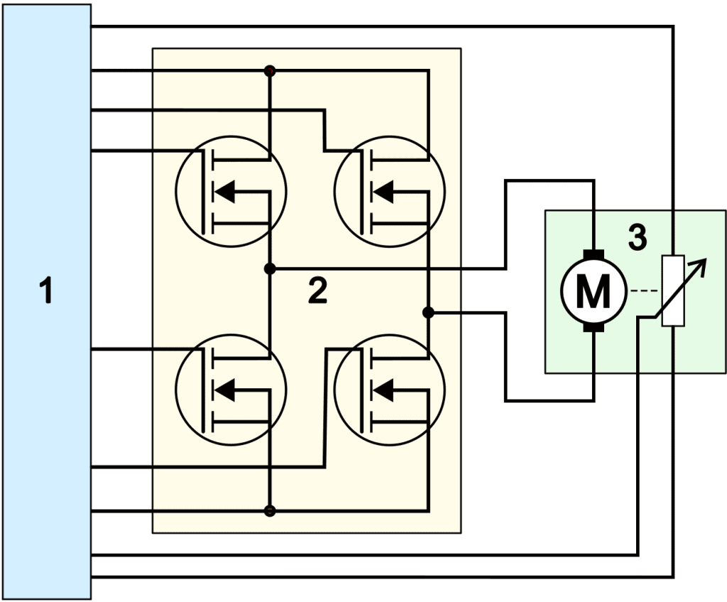
On the H-bridge page, examples of the various implementations of the H-bridge with transistors and FETs are described.
Besides passive actuators, we also encounter active and intelligent actuators. In the image below we see the circuit of these types.
For active and intelligent actuators, the ECU switches the current indirectly through the actuator. The transistor in the ECU is relatively lightly constructed, as the current it switches is negligible.
- Active actuator: the power transistor is not in the ECU, but in the actuator itself. An example of this is a coil (a pencil coil, or DIS coil with internal drivers). The active actuator is in this case the driver. The actuator gets a constant power supply and a constant ground, and the signal transistor in the ECU switches the power transistor on or off with a logical 1 or 0 (5 volts or 0 volts);
- Intelligent actuator: the actuator is equipped with its own ECU with a switching transistor. Communication between the two (or more) ECUs takes place through LIN-bus, where digital signals are exchanged. An example of an intelligent actuator is a windshield wiper motor. LIN-bus communication can exchange data such as: the current position of the wiper arms, speed, and movement to the home position.
Related page: