Introduction:
The advantages of the automatic transmission are that it increases ease of use, comfort, and safety. The change in gear ratio is as smooth as possible, without jolts. The automatic transmission shifts up to a higher gear sooner when accelerating gently than when the accelerator is fully pressed. If the latter is done, shifting up will not occur until just before the rev limiter. When the vehicle comes to a stop, it automatically shifts down to the first gear.
There is a fluid coupling or a torque converter mounted between the engine and the automatic transmission. For more details, see the separate chapter torque converter.
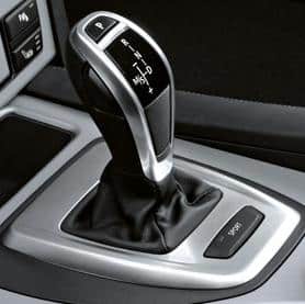
Gear Selector / Mountain Gears:
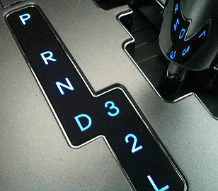
A car with an automatic transmission has a gear selector. By first pressing the brake pedal, the gear selector can be operated. Here is a list of its functions:
- P: Park (The output shaft is locked, the car no longer rolls away, and the engine can rev up)
- R: Reverse
- N: Neutral (The car is in neutral, the output shaft is not locked, so it can roll away if the brake pedal is released)
- D: Drive (The forward gear, the car will automatically shift up and down when accelerating)
- *S: Sport (The car will shift less aggressively so that more acceleration occurs with sudden throttle)
- *M: Manual (Allows manual shifting by moving the gear selector forward or backward to the + or -)
* is often optional and not present on every automatic.
Other car brands use the L, 2, and 3 positions for the driver to choose which gear the car should remain in. These positions are also called the “mountain gears.”
When one of these positions is engaged, the automatic transmission is set and held in a certain gear. This can be very handy when driving in the mountains. Normally, during descent, the automatic transmission in the “D” position shifts to a higher gear. Consequently, the transmission ratio becomes smaller, causing the car to descend faster. By engaging gears 3, 2 (1 or L), the transmission will operate in a lower gear (e.g., from the 5th to the 4th gear). The engine then revs higher, slowing down the car. More braking on the engine means less need for constant braking, which is essential with a trailer on a steep descent; otherwise, the brakes can overheat due to continuous braking.
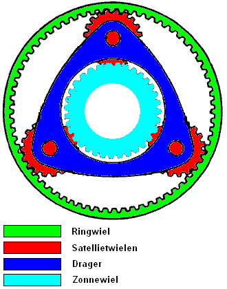
Single Planetary Gearset:
Planetary gearsets are used in various systems, namely in automatic transmissions, starters, overdrives, and hub reductions. A planetary gearset consists of the following components:
- Ring Gear
- 3 Planet Gears
- Carrier
- Sun Gear
To transmit torque with a single planetary gearset, the ring gear, carrier, or sun gear must be fixed. This component then acts as a reaction element. The planet gears serve only to bridge the distance between the sun gear and the ring gear.
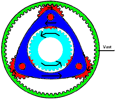
Example: The sun gear is connected to the engine and rotates at the same speed. The carrier is linked to the output shaft. The ring gear is fixed to the transmission housing. This results in significant reduction. That means: The sun gear is driving, the ring gear is the reaction element, and the carrier is driven.
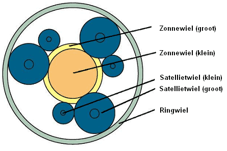
The sun gear (light blue, in the center) rotates counterclockwise. It drives the (red) clockwise rotating planet gears. These rotate in the ring gear and carry along the (blue) carrier.
As a result, the carrier rotates slower than the sun gear. That means the motion is slowed down.
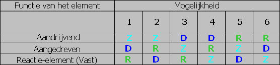
The table provides 6 different gear ratios. Not all gear ratios are usable in automotive technology. Usually, only 3 options remain.
For coupling and locking the different components, brake bands or multi-disc clutches are used. This way, different components can be coupled, resulting in reductions, accelerations, and changes in direction of rotation.�a0
In the latest systems, the computer ensures oil pressure is directed to the multi-disc clutches, allowing components to be locked. The theory of brake bands and multi-disc clutches is discussed further on this page.
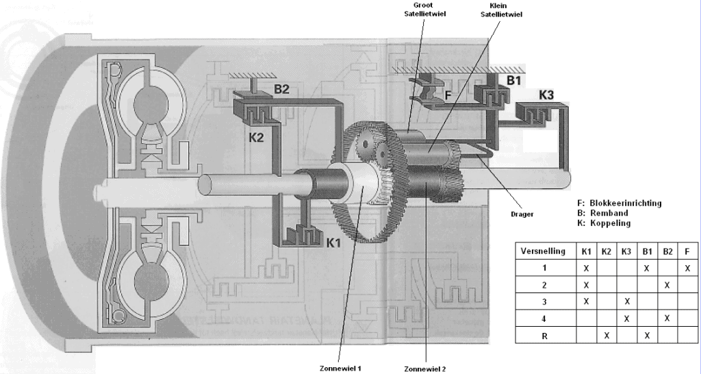
The image shows a schematic representation of four sets of planetary gearsets in an automatic transmission. There are three gearsets for forward gears and one for reverse. The red line indicates the direction of forces through the transmission; from the left (engine side with torque converter) through the complete part with planetary gearsets (black lines) to the driveshaft coupling. Four gearsets are used in the transmission, each with a Z, D, and R (sun gear, carrier, and ring gear).
On the page calculating reductions of planetary gearsets there is more information about the engagement and disengagement of planetary gearsets and the interconnection of various systems.
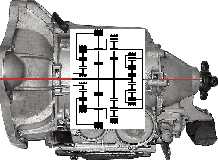
The planetary gearsets are symmetrical above and below the centerline. It can’t be any other way, as the internal mechanism rotates during operation.
To understand what happens when a gear is engaged, the driven parts in the planetary gear system of the illustration are also colored red.
In the illustration, speed 1 is engaged. To engage speed 1, a clutch must be engaged. This clutch is shown in blue. With the clutch engaged and one driven side of the planetary system, one part must also rotate. The sizes of the components determine the gear ratio in that case (think of a small input gear and a large output gear; the large gear then rotates slower. If the large gear had twice the number of teeth as the small gear, the ratio would be 1:2).�a0
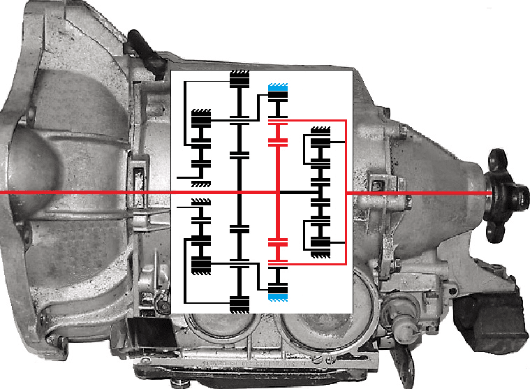
This largely applies to the automatic transmission as well; the sizes of the ring gear, sun gears, and planet gears vary in all four systems. Now you can probably imagine that when a different clutch is engaged (for example, from the left set), the speed of the output shaft changes. Click here for more information about calculating reductions of the planetary gearset.
Combined Planetary Gearset (Simpson Gearset)
In automatic transmissions, combined planetary gearsets are often used, where multiple planet gears or carriers are mounted on a single sun gear. This is the case with the so-called Simpson gearsets.�a0
The Simpson gearset has a wide sun gear and 2 ring gears. These ring gears are usually driven, reducing gear load compared to a driven sun gear. Consequently, the gearset can often be smaller. Nowadays, Simpson gearsets are not used as often. The Ravigneaux gearset is more popular among developers because it saves more space.
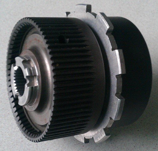
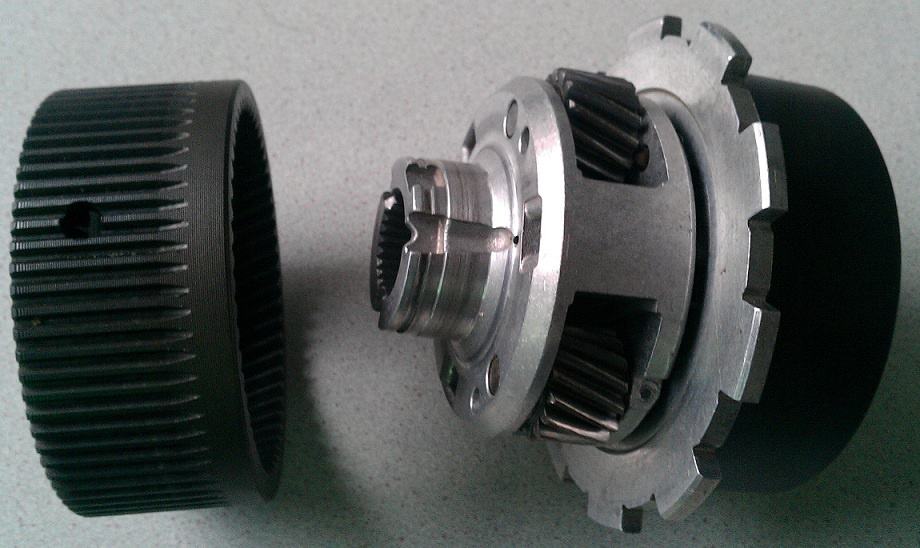
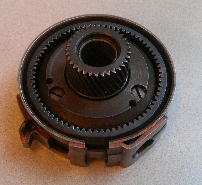
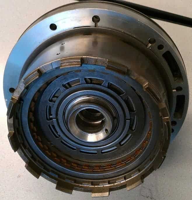
The image shows the planetary gearset as one compact unit. Visible are the ring gear (the left wide ring with teeth) and the carrier (the silver part).
The ring gear has been removed. Now the planet gears and carrier are visible. The 3 planet gears mesh internally with the sun gear and externally with the ring gear (which has been removed now). These gears are always interconnected.
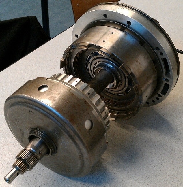
Here the carrier (with the planet gears) is removed from the sun gear. The sun gear is the gear on the right side.
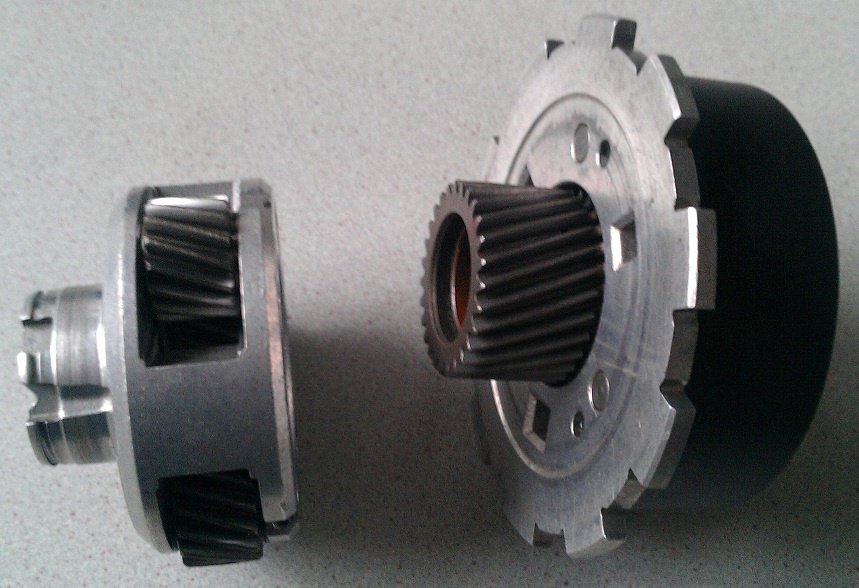
Here the dual sun gear is visible. The left part drove the planetary gearset shown in the images above. The right gear is the set next to it. This gives the designation “combined” gearset, or, the Simpson gearset. If the sun gear is singularly executed (only the left part) and there is only one planetary gearset, it is called a single or Ravigneaux gearset. The Ravigneaux gearset has 6 planet gears instead of 3 in this gearset, but this will be explained later.
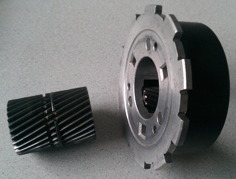
This is the other part of the combined gearset. The black ring gear on the left, the carrier with the planet gears in the middle, and on the right (inside) the sun gear.
Combined Planetary Gearset (Ravigneaux):
French engineer Paul Ravigneaux developed a compact planetary gearset in the late 1920s to create multiple practical gear ratios simply. This is known as the Ravigneaux gearset. It is now applied in many automatic transmissions.
This system is very compact because 2 planetary gearsets are combined into just one system. It consists of 2 sun gears, 3 large and 3 small planet gears, and 1 ring gear. Beside this is a side view.
In the image below, it is seen that the planet gears mesh with each other. The large planet gear connects with sun gear 1. The small planet gear connects with sun gear 2.
In the table, we see that when the first gear is engaged, clutch 1 (K1) and brake band 1 (B1) engage. This means sun gear 2 and the carrier with the planet gears are locked (these are driven). The ring gear is then the driver.
This provides the greatest reduction. A large reduction also means torque multiplication and a low wheel speed. The 1st gear is the best gear to accelerate from a standstill.
When the transmission shifts to the 2nd gear, brake band B1 is released, and clutch B2 is engaged. Now sun gear 2 and the ring gear are locked and driven. In this case, the carrier is driven. This combination of coupled components provides a less drastic reduction than the 1st gear and gives the precise gear ratio for the 2nd gear.
Multi-disc Clutches and Brake Bands:
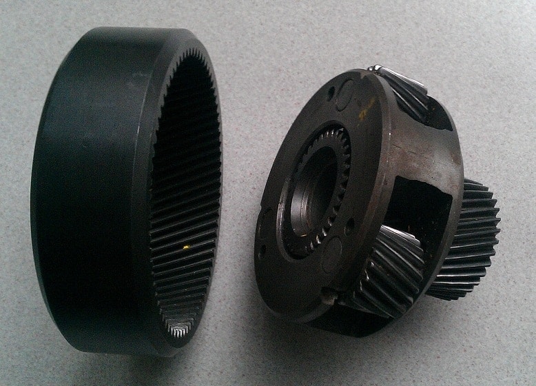
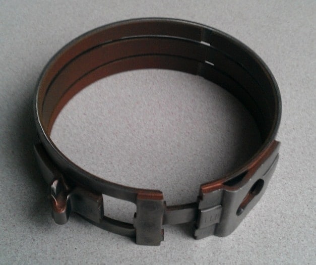
To lock various components (such as the sun gear, carrier, and ring gear), old transmissions used brake bands. Brake bands are made of iron and lubricated to minimize metal-to-metal contact and cooling. The images below show a brake band (left) and a brake band on the ring gear (right).
By squeezing the brake band with a hydraulic plunger (that extends), the ring gear is locked. Locking a particular part of the planetary gearset makes it driving and driven, thus engaging a specific gear.
Newer transmissions commonly use multi-disc clutches instead of brake bands.�a0A multi-disc clutch consists of several separate clutch plates arranged in a row, pressed together with oil pressure. This “couples” the clutch and locks the ring gear. The images below show the multi-disc clutches in disassembled condition. The parts are slid into each other. The teeth of the iron housings interlock.
Transmission Oil:
The transmission oil for automatic transmissions is usually of the type ATF (Automatic Transmission Fluid), but sometimes manufacturers require a different type of oil with other specifications. This must always be carefully checked, as the wrong oil in the transmission can cause excessive wear and premature failures. The oil level of the automatic transmission also needs to be periodically checked. If too low, the oil can overheat, causing it to age much faster, resulting in higher transmission wear. Checking the oil level can sometimes be as simple as using a dipstick, just like checking engine oil, but often the transmissions have no dipstick. Then the oil level must be checked by removing the fill plug while the engine is running and topping up until oil just starts to flow out. Depending on the manufacturer, the temperature may need to be checked first. Sometimes it should be done at the coldest possible oil, sometimes at oil between 30 and 50 degrees Celsius.
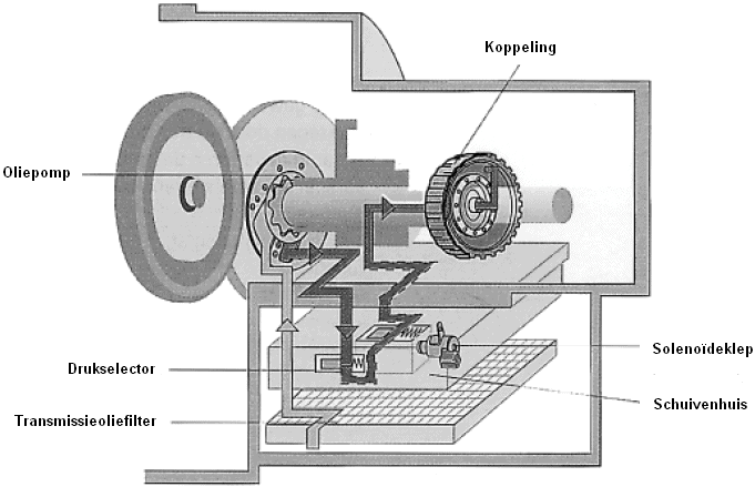
Oil Pump:
In the transmission, a gear pump or a crescent pump is often used. The pump in the image is a crescent pump. This pump is driven directly by the engine. The oil circulates whenever the engine is running, in all positions of the gear selector.

Control Unit:
The control unit ensures the pump pressure is regulated at a constant base pressure. Moreover, the control unit ensures the control valves are switched on and off at the right time.
Control Valves:
The control valves are operated by the gear selector position. In the P and N positions, the accesses are closed, and oil flows out of all lines. Consequently, all clutches and brake bands lose their oil pressure and are retracted by spring force. When the control unit sends a signal (e.g., to lock the ring gear for the first gear), a signal is sent to the solenoid valves (also known as solenoids). When a valve and thus also a slide of the slider housing opens, oil flows under high pressure to a plunger, which supplies oil to the multi-disc clutch or brake band. The pressure selector is a modulating valve that regulates the fluid pressure based on the throttle pedal. Through this oil pressure, a component in the automatic transmission is locked, enabling gear shifts.
Related Pages: