Topic:
Hydraulic directional valve:
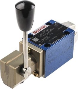
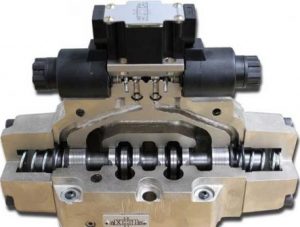
The hydraulic directional valve, also known as a valve spool, serves to control the flow direction of hydraulic oil. The directional valve can be operated manually or electrically.
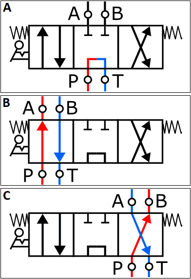
The following three images show the symbol of the directional valve in three different positions:
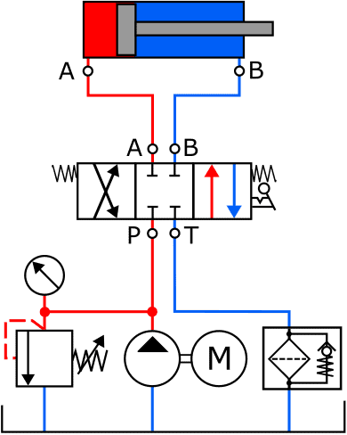
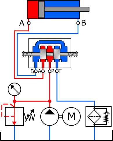
- A: the directional valve is in the neutral position. The hydraulic fluid from the pump is directed straight to the return;
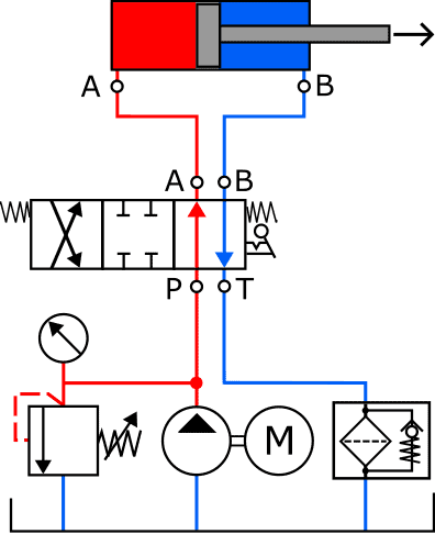
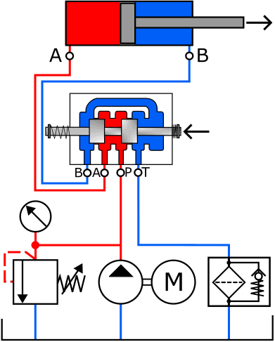
- B and C: the hydraulic fluid is directed to the cylinder. The difference between B and C is that they are cross-connected to each other, allowing the cylinder movement direction to be reversed. More on this later.
The depicted directional valve is a 4/3-valve, meaning it has four ports (A, B, P, and T) and three positions (center, left, and right).
The directional valve often has a central position, which is indicated by springs at both ends. The springs push the directional valve back to the neutral position once it is no longer operated.

The following three images show a manually operated directional valve (left), a cutaway directional valve (middle), and an animation of the operation (right). Explanation of the operation follows in the paragraph below the images.
As previously mentioned, the 4/3-directional valve can be set in three positions. In the following two images, the directional valve is shown in the neutral position. The piston is not actuated. On the left is the standardized symbol of the directional valve in the diagram, and on the right is the actual fluid circuit that is created in this position. The openings between B, A, P, and T are sealed off by the plungers.
When operating the directional valve, the fluid openings change. In this case, pump pressure is admitted to the left side of the piston (A). The oil on the right side flows back to the reservoir via ports B and T, through the filter. In the image with the actual fluid circuit, it is clearly visible that the directional valve is pushed to the left, allowing the opening between A and P (red) and B and T (blue) to let the hydraulic fluid flow.
- The hydraulic fluid enters via port P and exits the directional valve via port A to follow its path to the cylinder;
- The return channel is also opened: the fluid can flow to the reservoir via ports B and T.
Related page: