Introduction service brake:
The service brake can slow down and stop the vehicle. The service brake falls under the “air-consuming” section, which is colored yellow in the image below. On the page: basic air brake system, the different parts indicated in colors (blue, yellow, and green) are explained.
The service brake includes the following components: the foot brake valve, the load-dependent control valve (ALR), the relay valve, and the diaphragm cylinders on the front brake calipers and rear brake calipers or brake drums.
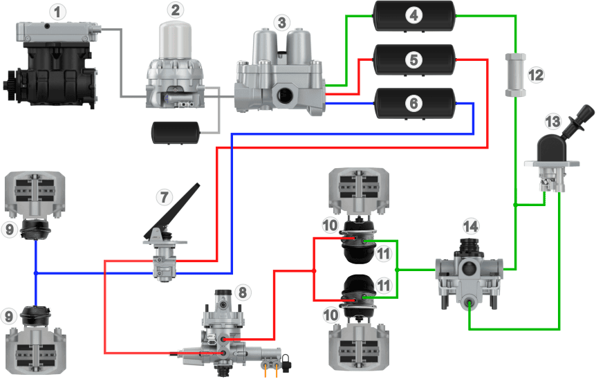
1. Air compressor
2. Dryer with wet tank
3. Four-circuit protection valve
4. Air reservoir circuit 3
5. Air reservoir circuit 1
6. Air reservoir circuit 2
7. Foot brake valve
8. Load-dependent valve (ALR)
9. Diaphragm cylinders (front)
10. Diaphragm cylinders (rear)
11. Spring brake cylinders (rear)
12. Check valve
13. Parking brake valve
14. Relay valve
- Blue: air supply
- Yellow: air consumption
- Green: parking/emergency brake
In the four-circuit protection valve (3), the brake circuits are separated from each other. In the image below, the brake circuits are indicated with colors:
- circuit 1 (red) is the brake circuit of the rear wheels;
- circuit 2 (blue) is the brake circuit of the front wheels;
- circuit 3 (green) is the brake circuit of the auxiliary or parking brake;
- circuit 4 is the brake circuit of the trailer or semi-trailer (not shown).
From the four-circuit protection valve (3), the service brake circuits of the front and rear brakes are separated. The air reservoirs (5 and 6) serve as storage to allow frequent consecutive braking. The service brake is operated by the foot brake valve (7). Controlled braking can be done with the foot brake valve.
The brake pressure from the foot brake valve is directed to the ALR (load-dependent valve, number 8). Here, the released air pressure is adjusted according to the vehicle’s load. The ALR directs the air pressure to the relay valve (9), where the air pressure from the ALR determines how much air pressure is allowed from reservoir (6) to the diaphragm cylinders (11) of the rear brakes.
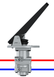
Foot brake valve:
With the foot brake valve, the driver operates two service brake circuits. These circuits are separated independently and can be controlled in small steps (dosed). After braking, the diaphragm cylinders are vented through the foot brake valve.
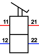
The symbol shows the inputs and outputs of the foot brake valve:
- 11 and 12: input 1 and input 2;
- 21 and 22: output 1 and output 2.
The image below shows the components in the foot brake valve. The explanation follows below.
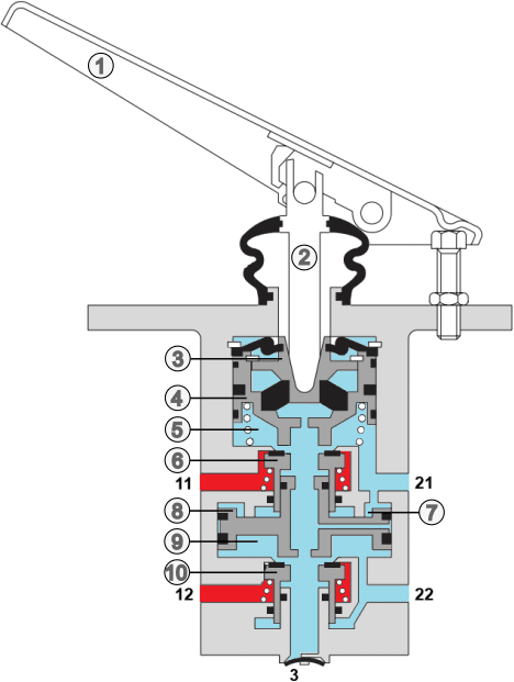
Legend
Components:
1. foot brake pedal
2. control piston
3. spring plate
4. upper piston tube
5. chamber A
6. middle piston tube
7. chamber B
8. control piston
9. chamber C
10. lower piston tube
Connections:
- 11: input 1
- 12: input 2
- 21: output 1
- 22: output 2
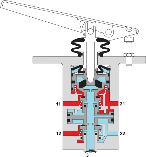
The following text refers to image 1 (above) and to images 2 and 3 (below the text). The red color indicates the supplied air pressure from the reservoirs, and blue indicates atmospheric pressure.
Image 1:
In the rest position, the middle and lower piston tubes (6 and 10) seal the inputs of the foot brake valve. There is no passage of air pressure from the input to the output. The springs (the cross sections of the springs are shown as white circles) push the piston tubes 4, 6, and 10 into their rest position.
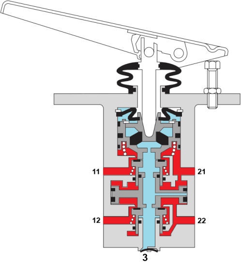
Image 2:
The driver operates the brake pedal (1) with the foot. The control piston (2) is mechanically operated and moves downward. The spring plate (3) and the piston tubes (4 and 6) are also moved downward. A passage forms between input 11 and chamber 5. Because the piston tubes are round, the air flows around them to output 21. Initially, pressure is built up in brake circuit 1. The reason that the pressure to the rear axle increases a few tenths of a second faster than the pressure to the front axle is that the circuit to the rear axle often contains more valves. By activating these valves slightly earlier, the brakes of the front and rear axles will still start braking at the same time.
Image 3:
The air pressure in circuit 1 of the rear axle exerts in chamber B (number 7 in the image above), where the lower control piston (8) is pneumatically pressed down. This way, the air flow to circuit 2 is not mechanically, but pneumatically controlled. The incoming air pressure from the reservoir enters via connection 12 and is allowed through to connection 12.
Circuit 2 is pneumatically operated when sufficient pressure has built up in circuit 1. If there is a leak in circuit 1, no compressed air flows into chamber B. The driver will have to press the brake pedal further down so that the middle piston tube (6) contacts the control piston (8) to mechanically transmit the braking motion to circuit 2.
After the brake pedal is released, the piston tubes are pushed back up by their spring force. Circuits 1 and 2 are closed again. The remaining air pressure in chambers A, B, and C flows out through connection 3 of the foot brake valve. This way, residual pressure is prevented from causing unwanted pressure in the diaphragm cylinders, which would result in the brakes being applied unintentionally.
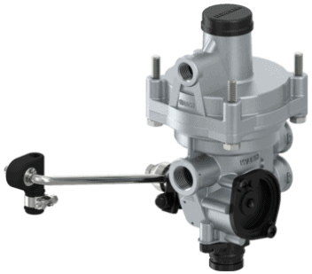
Automatic load-dependent control valve (ALR):
The brakes on the rear axle are not directly pressurized from the foot brake valve.
The weight on the rear axle determines the maximum braking force, so the braking force must be adjusted to the load. High brake pressure on an unloaded rear axle increases the likelihood of wheel lockup, and low brake pressure on a loaded axle barely slows the vehicle down.
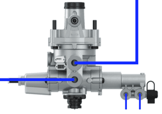
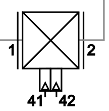
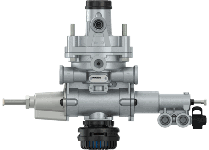
On the pneumatic ALR, we see the following connections:
- 1 and 2: input and output
- 41 and 42: control (airbag connections)
The ALR (number 8, the automatic load-dependent brake pressure regulator in the overview image) measures the load in one of two ways:
- mechanical: this type of ALR is mainly used on older vehicles or vehicles with leaf springs. By means of a lever connected with a cable or rod to the chassis, the height of the vehicle relative to the suspension is measured. On a loaded axle, the leaf springs will deflect, and the lever moves downward;
- pneumatic: the air pressure in the air springs is measured by the pneumatic ALR. In a loaded vehicle, the load and therefore the air spring pressure increases.
The ALR directs the – load-adjusted – air pressure to the diaphragm cylinders of the rear brakes.
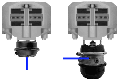
Diaphragm cylinder:
A diaphragm cylinder is a type of brake cylinder. The energy provided by the supplied air pressure is converted into movement in the diaphragm cylinder. This movement is converted into a force by means of a lever that presses the brake lining against the brake disc or drum.
The force with which the brake lining is pressed depends, among other things, on the lever ratio and the air pressure in the diaphragm cylinder.
In the image next to this, we see two diaphragm cylinders:
- left: diaphragm cylinder of the front axle;
- right: diaphragm cylinder with the spring brake cylinder underneath for the rear axle.
The spring brake cylinder is discussed on the page: auxiliary and parking brake.
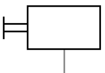
Next to the images of the diaphragm cylinders, we see the symbol.
In the next image, we see a cross-section of a diaphragm cylinder. The compressed air from the foot brake valve or relay valve enters chamber 1 on the left of the diaphragm (2). The air pressure pushes the diaphragm against the spring force of spring (3) to the right. The pushrod follows this movement and pivots lever (5) on its axis. At that moment, braking occurs.
When the brake is released, the air pressure on the left of the diaphragm decreases, and the spring pushes the diaphragm and the pushrod back to the rest position.
A diaphragm cylinder on the rear axle works on the same principle, but there is also a parking brake cylinder in the housing.
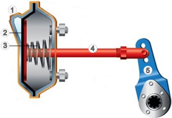
Legend:
1. air connection
2. diaphragm
3. spring for rest position
4. pushrod
5. lever
The animations below show the outward stroke of the diaphragm cylinder operating the lever, and an S-cam that pushes the brake shoes against the brake drum when rotated. Note: the animations are not synchronized. In reality, during the outward stroke of the diaphragm cylinder, the S-cam moves the brake linings against the drum.
Related page: