Introduction:
The relay is widely used in automotive electronics within the current circuit of consumers where a lot of current flows through. The higher the current, the thicker the wiring must be executed. The diameter of the wire determines the maximum current capacity. We want to avoid thick wires as much as possible because wiring harnesses would become too large and susceptible to faults. A second, and even more important reason to use relays, is the control by an ECU. High current is associated with more heat. We want to keep the heat outside of the ECU as much as possible. Examples of electrical components controlled by a relay include:
- Engine cooling fan;
- Horn;
- Rear window defogger;
- ECUs;
- Injectors and ignition coil (gasoline engine);
- Fuel pump;
- Low, high, and/or fog lights.
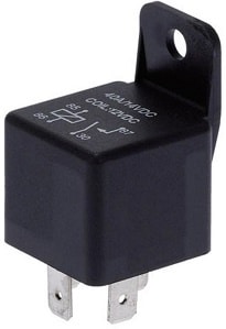
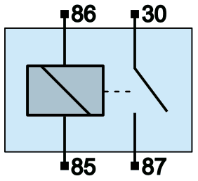
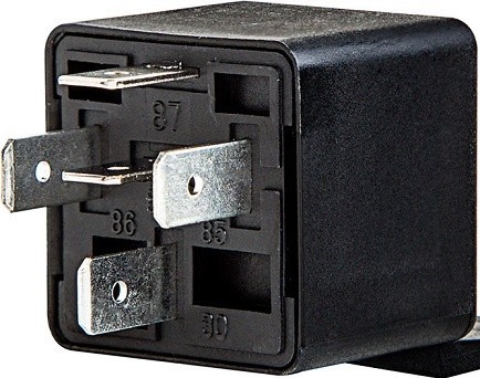
The following two images show a diagram of the relay and a picture of a real relay. On the relay, we find four connections with standard DIN codes:
- Control current input (86)
- Control current output (85)
- Main current input (30)
- Main current output (87)
A relay transforms a small control current into a large main current. That is a standard phrase that many students and mechanics know how to say. However, when it comes to measuring a relay circuit, confusion often arises about the codes: where does the control current and main current flow? And how should one measure to verify if the relay is working properly? The following paragraphs describe the operation of the relay, the voltages you should measure on a properly functioning relay, and how to diagnose faults.
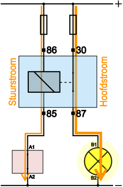
The image below shows a deactivated and an activated relay.
- Relay deactivated:
The switch (red housing) is located in the circuit between the output of the relay (terminal 85) and the ground of the battery (chassis). In reality, this switch may be located on the dashboard, for example, the fog light switch.
- Relay activated:
When the driver operates the switch, the contacts close. This closes the current circuit on the control current side. A current flows from the positive terminal of the battery, through 86, the coil of the relay, and via 85 and the switch to ground. As current flows through the coil, it becomes magnetic and pulls the switch between pins 30 and 87 closed. A closed main current circuit now also forms there. A main current flows via the positive terminal of the battery, through the fuse to terminal 30 of the relay, after which the current is conducted via terminal 87 to the consumer. The consumer turns on.

In the images, a lamp is often shown as the consumer. In reality, other electrical consumers/actuators can take this place. For a relay circuit, it does not matter what type of consumer is being controlled.
The control current through a relay usually ranges between 150 and 200 mA (0.15 – 0.2 A). The main current can reach up to 20 or 50 A. The maximum allowable main current is often indicated on the casing of the relay.
Relay Circuits:
A relay enables a control current with a low current level to be activated by a switch that can be operated manually, or by a control unit (ECU). The circuit with the ECU is found in most modern vehicles.
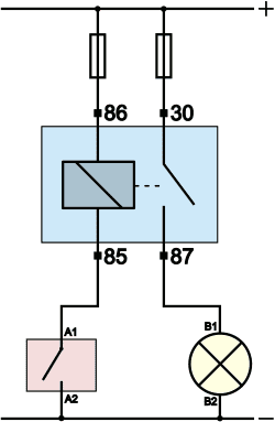
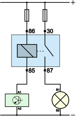
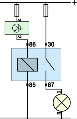
A relay can be + switched or ground switched. For the functioning of a relay, it does not matter if it is activated by switching the power or ground: once the relay receives both positive and negative, current flows through the coil. The three images below show a ground switching with a switch and ECU, and a + switching.
The versions where a control unit toggles the control current on and off offer several advantages:
- The driver can instruct the control unit to switch the consumer on. This can be done with a small switch on the dashboard or via the digital onboard computer (possibly via the multimedia screen);
- The ECU can toggle the relay itself based on a sensor signal (e.g., engine temperature high, fan on), or deactivate the fuel pump when an accident is detected by the airbag ECU. The regulation by the ECU thus offers comfort but also a higher level of safety.
In the diagrams on this page, terminal 86 is considered as the input and 85 as the output. In practice, it is common to see manufacturers reverse these terminals: 12 volts enter at 85 and 86 is connected to ground. The relay can then again be either + switched or ground switched. This can often be found in the diagram, otherwise measurements will determine how the relay is switched in the vehicle.
Measurements with a deactivated and activated relay:
In the introduction, it was described how the control current and main current are formed. When a consumer is no longer functioning, typically the error memory is read first and the voltage across the consumer is measured. With a V4 measurement, it can be detected if there is a transition resistance or interruption in the power or ground. If a wire is broken, a fuse is faulty, or a switch remains in the “open” position, we measure a value in V3 and/or V4 that is unequal to 0 volts: in other words, something is wrong. This paragraph shows measurement examples to check the voltages on the relay. We assume the situation where 86 is the input and 85 is the output of the control side. In the previous paragraph, it was explained that manufacturers sometimes reverse this.
Relay deactivated:
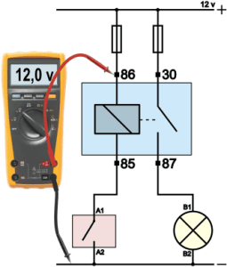
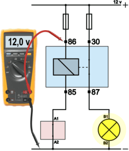
This text relates to the measurements shown in the four images below. With a deactivated relay, we use the multimeter to measure the voltage on the four pins (86, 85, 30, and 87) relative to the ground (chassis or with an alligator clip on the negative terminal of the battery).
- Measurement 1: on the input of the control side of the relay (pin 86) is 12 volts (or 24 volts in a commercial vehicle);
- Measurement 2: since the relay is deactivated, the voltage is not used, so there is 12 volts on pin 85;
- Measurement 3: on the input of the main current side (pin 30) is 12 volts;
- Measurement 4: because the relay is not energized, the switch in the relay remains open, so there is 0 volts on pin 87.
| Terminal 86: | 12 v |
| Terminal 85: | 12 v |
| Terminal 30: | 12 v |
| Terminal 87: | 0 v |
Relay activated:
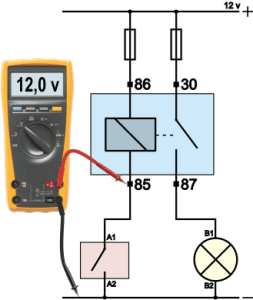
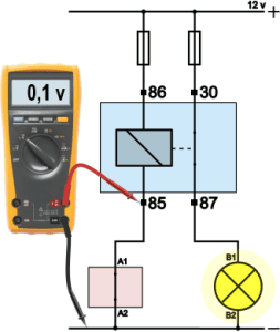
The switch is closed. Terminals A1 and A2 are connected. The control current circuit is closed and control current flows. With an activated relay, we once again measure the voltage on the four pins (86, 85, 30, and 87) relative to the ground.
- Measurement 1: on the input of the control side of the relay (pin 86) is 12 volts;
- Measurement 2: since the relay is activated, the voltage is used and converted into magnetism, so there is 0.1 volts on pin 85;
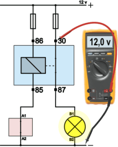
- Measurement 3: on the input of the main current side (pin 30) is 12 volts;
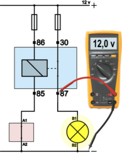
- Measurement 4: because the relay is energized, the switch in the relay is closed, and there is 12 volts on pin 87.
| Terminal 86: | 12 v |
| Terminal 85: | 0.1 v |
| Terminal 30: | 12 v |
| Terminal 87: | 12 v |
Troubleshooting:
For a malfunctioning consumer/actuator, we can measure the voltages on the relay’s connections to trace the cause of the fault. If a relay does not trigger, the cause may be a defective relay, but if the fuse is defective and the relay does not receive input voltage, it cannot switch anything onward. With four measurements on the relay (always relative to ground), we can rule out many possibilities and search more specifically for the exact interruption. In the examples below with potential malfunctions, the red X indicates the location of the fault, and the value on the multimeter indicates the voltage difference between the measured points.
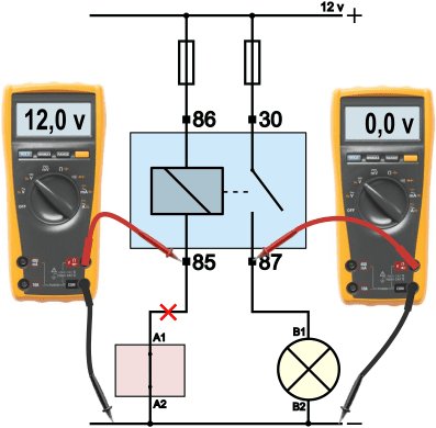
Fault 1: the relay does not switch
The relay is grounded by the switch but no control current flows. Consequently, there is also no main current. The voltage on pin 87 remains 0 volts. This prompts measuring the other pins on the relay. After activation, the voltage difference between pin 86 and 85 is measured, showing 12 volts. In this case, the coil is broken.
The voltage difference across a properly functioning relay is 12 volts, as the voltage is consumed. Therefore, this measurement seems correct, but it is not. With a broken coil, we also measure 12 volts, as there is a 12 volt difference between the measuring probes: 12 volts enter the red probe, and 0 volts are on the black probe via the closed switch.
When it is suspected that the coil in the relay is broken, resistance can be measured. The relay must be disassembled and should not be part of the current circuit anymore. On the loose relay connections, the resistance between pin 86 and 85 can be measured.
- Resistance through the coil: around 60 to 80 ohms: okay
- Resistance through the coil: infinite (1. or OL): interruption

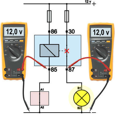
Fault 2: the relay does not switch
When operating the switch (red housing) or after the ECU is activated, the consumer remains off. Measurements on pin 85 show 12 volts relative to ground. This allows us to conclude the voltage is not consumed in the coil, so the coil has not become magnetic.
A differential measurement between pin 85 and pin A1 on the switch will indicate whether the wire is broken or if the problem lies within the switch:
- Voltage difference between 85 and A1: 12 volts: wire broken
- Voltage difference between 85 and A1: 0 volts: the issue is not in the wire.
If the wire is intact, there is 12 volts on both sides of the wire, resulting in a difference of 0. If 12 volts are measured across the switch (A1 relative to A2), the interruption is within the switch. In other words: the switch remains open. These 12 volts are also measured when the switch is unoperated.
Fault 3: consumer remains activated.
A possible customer complaint is that the vehicle’s cooling fan continues to run, even when the vehicle is parked and has been turned off for some time. The customer noticed this from the sound originating from the fan. Another possibility is a customer reporting a parasitic drain issue: the battery is drained after a relatively short period, even though the condition of the battery and the charging system are good. This is referred to as parasitic drain or a parasitic consumer.
The measurements show that no control current flows (12 volts on pin 85), but the main current does flow.
In this case, the cause is a “sticking” relay switch. The switch between 30 and 87 remains closed, even though the coil is not magnetic. The cause could be age, where contacts have become burnt.
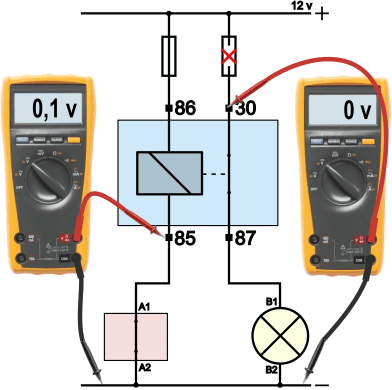
Fault 4: the relay switches on, but the consumer does not function
When the relay is switched on, you usually hear the switch between 30 and 87 close. Pin 86 shows 12 volts and pin 85 0.1 volts relative to ground. This means that a control current flows and the voltage is consumed in the coil. The control current circuit is in order.
On pin 30, there is 0 volts relative to ground. The relay has indeed closed the main current circuit, but if nothing enters, nothing can be passed on. In this case, the fuse is defective.
A fuse does not fail just like that. There has been an excessively high current through the fuse, so it is important to search for the cause. For example, too many consumers may be connected to the fuse (consider multiple 12-volt connections for accessories), or a fuse with an incorrect value has been previously installed.
Fault 5: the relay switches on, but the consumer does not function
When the voltages on the relay’s four terminals are correct, you know the relay is being controlled properly, the input voltages are good, and the relay functions correctly. The voltage on pin 87 becomes 12 volts when the relay is on and returns to 0 volts when it turns off.
When the consumer still doesn’t work, it’s likely that the consumer itself is defective, or there is a wire break between the relay and consumer, or between the consumer and ground. A V4 measurement across the consumer will help pinpoint the location of the fault.
When the voltage across the consumer is equal to the battery voltage, 12 volts, then the consumer is defective. In this example, the filament of the lamp is broken.
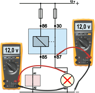
Fault 6: the relay switches on, the consumer operates, but not well enough
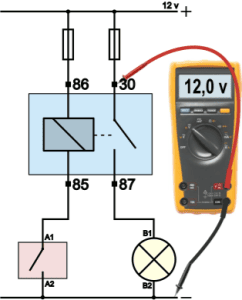
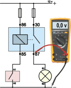
The consumer does work, but at half power. With a lamp, this is recognizable by dim lighting, which especially stands out when multiple lamps are on and one deviates in light intensity. An actuator might be an electric motor that spins slowly, or a horn that produces too little sound. In that case, we perform a V4 measurement on the main current section. The relay switches the consumer on, so we need not focus on the control current section.
With the V4 measurement in the bottom left image, we see that the lamp operates at 9 volts, while the battery voltage is 12 volts. In V3 (from positive battery to positive lamp), a voltage difference of 3 volts is measured. This is lost in the positive circuit. Further measurements will determine if the voltage loss occurs before the relay, in the relay, or after the relay (between pin 87 and B1). In the lower-right image, we see that the voltage difference across the relay (30 in relation to 87) is 3 volts. The voltage loss occurs in the relay. The contacts of the switch are dirty or burnt, causing a transition resistance.


Summary:
Due to detailed fault descriptions and large images, we summarize the different faults with causes:
- fault 1: the relay does not turn on because the relay coil is broken. Current can no longer flow through the coil, preventing it from becoming magnetic. Resistance measurement can trace the break: around 60 to 80 ohms is good, infinite is a break;
- fault 2: the relay does not turn on because the wire between pin 85 (control output) in the switch is broken. The voltage on pin 85 remains 12 volts, even when it’s activated;
- fault 3: the relay sticks, keeping the consumer on. The voltage on pin 87 remains 12 volts, even if the relay is not controlled. This may be noticed by sight or sound, but for a “silent” (parasitic) consumer, the battery is drained;
- fault 4: the relay switches, but due to a defective fuse, the consumer does not work;
- fault 5: as the consumer is defective, it no longer functions. With the four measurements on the relay, it is ruled out that the issue lies with control;
- fault 6: a transition resistance results in a less efficient consumer/actuator. The V4 measurement can trace the location of the transition resistance. In the example, a voltage difference is measured across the switch between 30 and 87, indicating voltage loss due to transition resistance in the relay is present.
Conclusion:
With the six possible fault causes encountered in vehicles, the importance of knowledge and skills to measure voltages on the relay is highlighted. Measuring the four terminals quickly provides a direction for troubleshooting, helping determine if there is an issue at the control input or output, main current input or output, or within the relay itself.
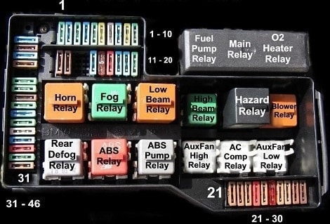
Locations of Relays:
Relays are often mounted in one place in the car. This can be in the fuse box (as shown in the image) or on a separate relay board. There may also be relays installed under the hood, such as the engine cooling fan relay. The relay positions can be found in the vehicle’s instruction manual and/or workshop documentation.