Topics:
- Injection system
- Ignition system
- Idle control
Injection system:
The BMW engine was already equipped with a multipoint injection system. In this case, we do not need to look for suitable injectors and modify the intake manifold, as with the Land Rover project.
Since the engine has been out of use for years and the gasoline present is outdated, it was initially decided to clean and test the injectors.
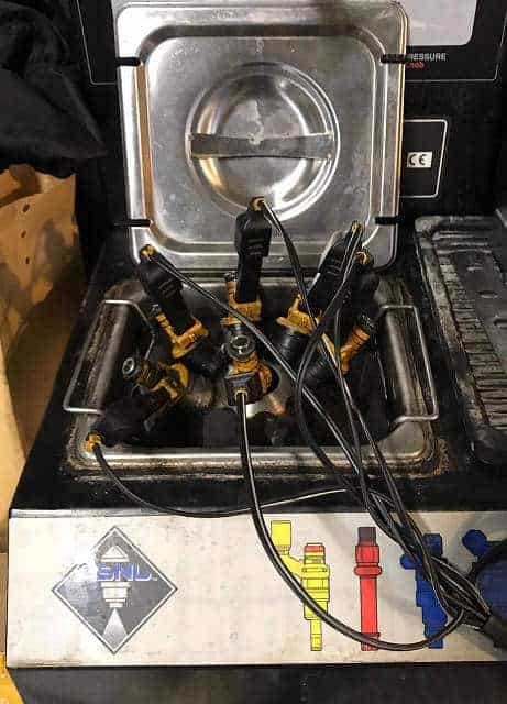
It would of course be nice if the engine started immediately the first time it is started. Since the engine has been stationary for years with outdated gasoline, it was still in question whether the injectors would function properly. It would be a shame if the engine didn’t start the first time because one or more injectors didn’t spray properly. At that point, you don’t know if it’s due to the injection timing, the injection quantity, ignition timing, you name it. Therefore, it was decided to clean the injectors in an ultrasonic bath with cleaning fluid and then test the flow. The image below shows the cleaning procedure. Thanks to Manuel Nunes Pombo and D.F. Krijgsman Engine Revisions B.V.
After cleaning, the injectors were tested in a test setup for the injection quantity (flow) and the leak test when there is no control. The videos below show the image during the injection and the leak test.
It can be seen that one injector doesn’t spray at all and other injectors don’t have a good spray pattern. During the leak test, fuel continues to leak from two injectors. Even after three cleanings, it didn’t get any better. If we hadn’t checked this and made an initial start attempt, we would have wasted a lot of time looking for possible causes after it ran poorly and stalled.
Since tuning mainly involves changing the map fields related to injection, the fuel supply must of course function properly. The ignition has already been completely renewed; a new coil, spark plug wires, and spark plugs, so it was decided to also install six new injectors. The injectors remain sealed in the packaging for as long as possible; they will be installed in the intake manifold just before the first engine start.
Ignition system:
The original ignition system with distributor ignition is replaced by an electronically controlled, triple DIS coil with internal drivers. The coil is sourced from a Volkswagen V6 engine (engine code AQP).�a0
The diagram below shows the pin configuration of the coil (component code N152).
The coil is provided with a control signal by the engine control unit (J220). Instead of the original control unit, the MegaSquirt controller will provide this signal.
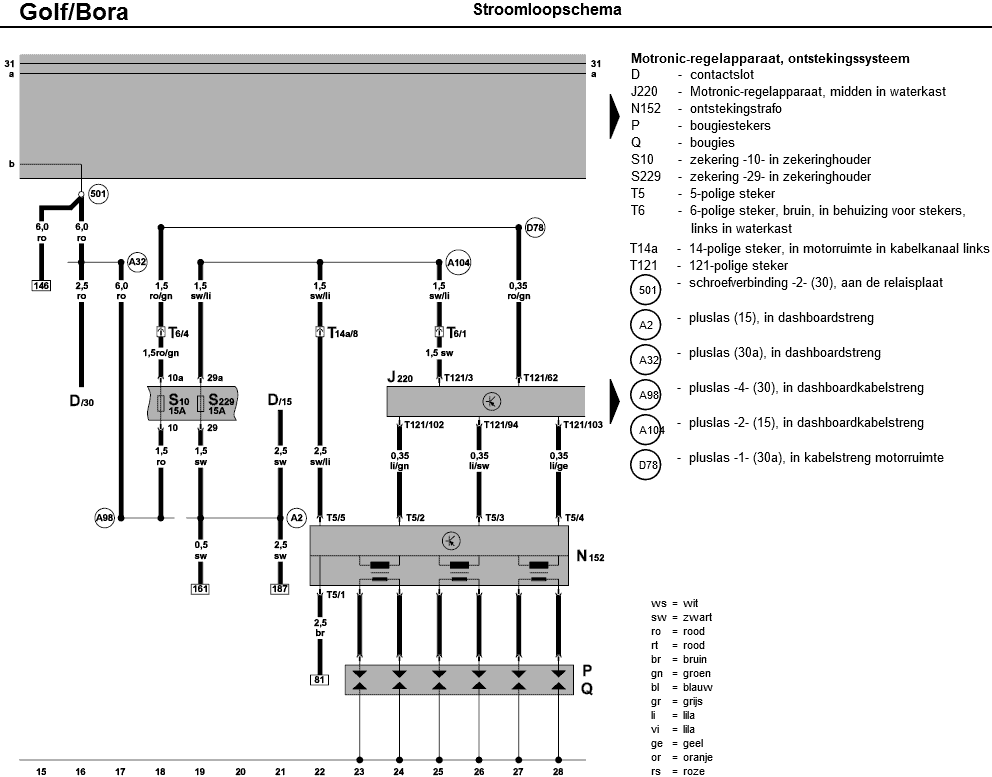
- ground;
- ignition signal spark A (cylinders 1 and 6);
- ignition signal spark B (cylinders 3 and 4);
- ignition signal spark C (cylinders 2 and 5);
- plus (12 volts).
The following properties are also known and can be directly inputted into TunerStudio:
- Spark output: going high;
- Number of coils: 3, wasted spark;
- Cranking dwell: 4 ms;
- Nominal dwell: 2.3 ms.
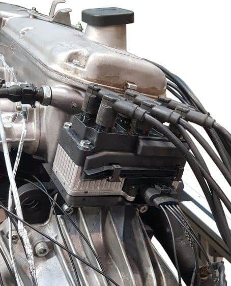
To mount the coil as close to the engine as possible, we made a custom bracket. The bracket is mounted at the bottom with the gearbox bolts on the bell housing. The coil is attached to the bracket with four M6 bolts and nuts.
Idle control:
A two-wire PWM valve can be directly connected to the MSII ECU. The controller sends a pulse-width modulated signal to the PWM valve which opens against the spring force. When the duty cycle becomes smaller or falls away, a spring in the PWM valve closes the control valve. The second connection is for the power supply.
The BMW engine’s PWM valve has three connections:
- PWM for the positive edge;
- PWM for the negative edge;
- Ground.
The MSII ECU sends the PWM signal to the connection for the positive edge. The valve opens but does not close anymore. The internal spring is missing. A negative PWM signal should close it. To make closing possible, in this case, a 35 ohm, 50 Watt resistor is mounted between the ground connection of the PWM valve and a grounding point of the engine. When this resistor is applied, a small current always runs through the PWM valve, which acts as a kind of “electric spring.” The PWM signal that the controller sends to the valve overcomes the spring force of the small current. When the signal decreases or falls away, the current pulls the valve closed again.
The 35 ohm resistor becomes very hot and is effectively a loss of energy. Manufacturers try to minimize such losses. In this case, aside from searching for a different type of PWM valve, we have no other choice. Because the resistor gets so hot, it will be mounted on the metal of the engine frame. Through this contact, the resistor dissipates its heat.