Introduction:
The parking brake is often referred to as a “hand brake” because the lever in many cars must be pulled by hand. The image below shows the parking brake with a hand brake lever, brake cables, and drum brakes. When the driver pulls the handbrake lever upwards, an internal mechanism locks the lever in place. Once engaged, the front handbrake cable is pulled tight. The left and right handbrake cables are connected to the front cable via a compensator bracket. The compensator bracket allows play to be adjusted; consider one stretched hand brake cable or an improperly adjusted mechanism in the drum brake. If one cable is longer than the other for that reason, the compensator bracket will slant. Still, both brake cables will be pulled equally tight when the handbrake lever is engaged.
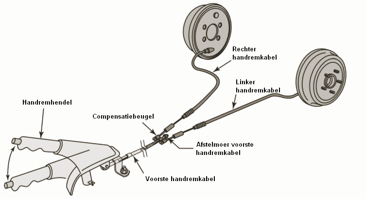
The front handbrake cable is connected to the compensator bracket by an adjustment nut. We can turn this adjustment nut for the following reasons:
- Adjusting the handbrake. This might be necessary if the handbrake lever needs to be pulled up, for example, eight notches before the brakes lock.
- Dismantling handbrake cables, handbrake mechanism in drum brakes or caliper. Disassembly of certain parts is often not possible without relaxing the cables.
The explanation above relates to the common cable-operated parking brake. There are also other versions available today, such as foot-operated parking brake cables and the electric parking brake. This page describes the different versions of the parking brake.
Drum Brake as Parking Brake:
When a car is equipped with drum brakes on the rear axle, a parking brake mechanism is integrated. By pulling the handbrake cable (see the red arrow on the left of the cable), the dark blue lever in the image is pulled to the left at the underside. The lever pivots in the right (light blue) brake shoe and pushes the lining against the (yellow) brake drum.
The white spacer is connected to the dark blue lever and the left (light blue) brake shoe. The lever’s motion is transferred, so that the lining of this brake shoe is also pressed against the drum.
When the parking brake cable is relaxed, the �a0spring on the handbrake cable pushes the inner cable back to its starting position. The�a0springs on the brake shoes pull the shoes and linings back together, so that the linings are no longer in contact with the drum.
Due to wear and tear on the brake drum, the diameter on the inside becomes slightly larger. The brake shoes then move further outward to make contact with the drum. During maintenance and repairs, we need to remove the brake drum from the axle. In most cases, the drum cannot be removed without first resetting the brake shoes.
The mechanism contains a ratchet wheel or a pawl that must be turned back or shifted using a flat screwdriver. The image shows the screwdriver’s movement to turn the ratchet wheel. Turning the ratchet wheel in one direction causes the shoes to move closer together; the spacer becomes smaller, and the springs on the brake shoes pull the shoes together. Once the ratchet wheel is turned back far enough, the brake drum can be taken off.
During assembly, we must of course turn the ratchet wheel the other way, so the shoes are correctly positioned again.
Disc Brake as Parking Brake:
A car with rear disc brakes can be equipped with a parking brake mechanism. In the following image, the caliper with the parking brake lever is visible. The lever is connected via a cable to the parking brake lever inside the car. When the driver operates the lever, the caliper lever turns, activating the mechanism inside. The parking brake uses the same piston as the service brake, which operates via the hydraulic brake circuit. During operation, the piston presses the inner brake pad against the disc. The “floating caliper” is pulled towards the piston side due to the guide pins, so the outer pad is also pressed against the disc.
Read more about the disc brake.
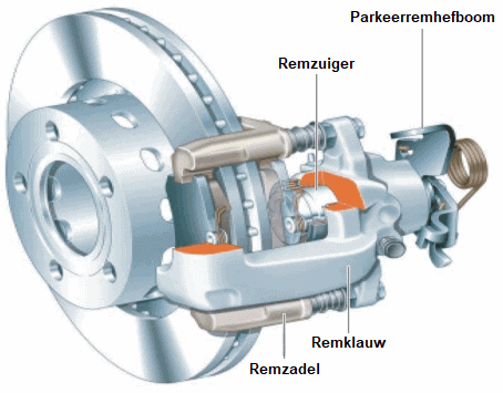
When the parking brake is activated, the lever is turned via the brake cable. The operating shaft and cam disk are connected to the lever and turn with it. This operating shaft creates a lateral movement that pushes the brake pad against the disc. The lateral movement arises because the cam disk, when turning, rolls over three balls along a progressively thicker section. If the driver pulls the parking brake even harder, the cam disk pushes the pushrod further outward.
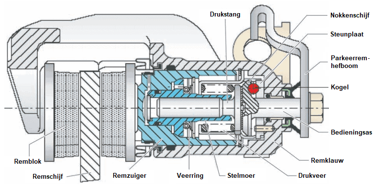
The adjustment nut and pressure spring are responsible for compensating for brake pad wear. As the pads wear and become thinner, the adjustment nut acts as a “self-adjusting mechanism” to take up the slack. When replacing the brake pads, the piston must be wound back using special reset tools for this reason.
Combination of Disc Brake and Drum Brake:
The previous paragraphs have described two different types of braking systems: the drum brake and the disc brake. The service brake (operated hydraulically via the foot pedal) is in these versions combined with a parking brake mechanism.
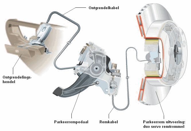
A number of car manufacturers (e.g. BMW and Opel) combine these braking systems on the rear axle. The disc serves as the service brake. The inside of the disc acts as a drum for the parking brake. This is clearly seen in the image by the brake shoes. The cable operates the drum brake mechanism to decelerate or lock the disc.
An alternative operating mechanism is also shown. The driver operates the parking brake by pressing the parking brake pedal, which is located far left near the A-pillar.
When the parking brake pedal is pressed, a locking mechanism ensures it stays depressed. Pressing the pedal harder allows it to move further down with more “clicks” and apply more pressure to lock the parking brake.
To release the parking brake, the driver must pull on the release lever. The lever is connected to the release cable interfacing with the mechanism behind the parking brake pedal. The parking brake will release completely and the pedal will snap back up.
A similar mechanism may be implemented without the release lever. Manufacturers such as Toyota and American-made vehicles feature a parking brake pedal with automatic release. With the active parking brake, the driver can release it by pressing the pedal once more.
Electromechanical Parking Brake with Motor on the Caliper:
Vehicles may be equipped with an electromechanical parking brake. The driver can operate the motor on the rear calipers using a button on the dashboard. Additionally, the vehicle can control the parking brake mechanism when standing still on a hill. This function is called “hill hold.” The ECU automatically operates the parking brake while stationary and while driving off, to prevent the vehicle from rolling. The driver can take their foot off the brake pedal.
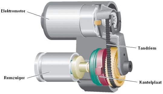
The rear brake calipers are equipped with an electromechanical mechanism that transfers the rotation of the motor to the brake piston.
The motor drives a gear via a toothed belt transmission, which is connected to a tilt plate. A spindle is attached to the tilt plate. The spindle is essentially a worm gear that can turn left or right, depending on the motor’s rotation direction. A large spindle nut is threaded onto the spindle, which presses against the inside of the piston. Rotating the spindle causes the spindle nut to move in or out.
The below images show the electric parking brake when at rest (left) and engaged (right). The spindle is turned, causing the spindle nut to push the piston against the brake pad. Since a floating caliper is used, both pads are pressed against the disc. In this scenario, the brake is engaged.
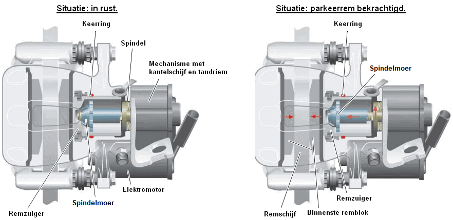
When the parking brake is deactivated, the motor drives the spindle to rotate the spindle nut back inward. The spindle nut does not pull the piston back in; these parts are not attached to one another. The piston is pulled back into its rest position by the deformed seal.
The parking brake is primarily operated manually by pressing a button on the dashboard, or through automatic control when the ignition is switched off. The schematic below shows the electrical components of the VW Passat 3C.
The control unit for the parking brake (J540) receives a signal via the parking brake switch (E538) when it is operated by the driver. The power wire at the lower part of the internal switch (red) is then connected to the control unit’s signal terminal (green wire). With a voltage on this input, the ECU recognizes that the switch is operated.
The control unit powers the motors on the calipers. These wires are shown in blue and brown in the diagram. The polarity may be changed to reverse the motors’ direction.
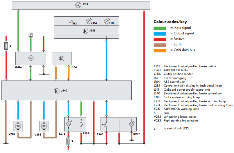
In addition to the signal from the parking brake switch, the parking brake control unit (J540) also receives information from other components:
- ABS computer (J104) to pass on the vehicle speed. The parking brake can be restricted or cannot be operated while driving. It can also assist during an emergency stop and the auto hold feature.
- Clutch position sensor (G476): the driver must engage the clutch pedal to disengage the parking brake.
- Auto hold switch (E540): if the vehicle is equipped with auto hold, the parking brake is applied automatically when stationary on a hill. Signals from the ABS computer and tilt detection are among those used for this function.
The parking brake control unit provides the instrument panel (J285) with information to activate the warning/fault light and buzzer.
Electromechanical Parking Brake with Cables to the Motor:
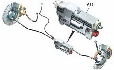
In another design of the electromechanical parking brake, there are no motors attached to the calipers but one central motor mounted on the chassis near the rear axle.
The parking brake actuator is connected to the calipers via cables. The system thus shares similarities with a manually operated parking brake.
The driver operates this actuator by pressing a button on the dashboard. The parking brake control unit activates the motor to tighten or release the cables.
When parked on a slope, an automatic regulation controls the actuator to prevent the vehicle from rolling away.
Related pages: